


 Tech-led.com


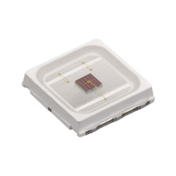
UV LED
High-Power UV LED Emitters (308–420 nm)
Marubeni offers high-power UV LED emitters spanning 308–420 nm, including UV-B LEDs and 365 nm LEDs for curing and inspection applications.
UV-A and UV-B Coverage
Our UV LED lights cover UV-B and UV-A ranges, ideal for industrial, medical, and scientific uses. Each device is built with AlInGaN MOCVD epitaxial wafers, ensuring high optical power and reliability.
Standard Wavelengths
Available wavelengths include:
UV-B: 308 nm, 310 nm | UV-A: 325 nm, 340 nm, 365 nm, 375 nm, 385 nm, 395 nm, 405 nm, 415 nm, 420 nm
Product Formats
Choose from bare UV LED chips, SMD packages, through-hole lamps, metal-can packages and UV LED arrays.
Custom UV LED arrays tailored to wavelength, power, or packaging requirements are also available.
SMD
| Product # | Discontinued? | Datasheet | Wavelength (nm) | Package Type | Package Size | Forward IF(mA) Current | Total Radiated Power Po(mW) | Viewing HalfAngleΘ1/2 (degree) |
|---|---|---|---|---|---|---|---|---|
| SMBB515V-1100-03 | No |

|
515 | SMD | 5mm x 5mm | 350 | 230 | 22 |
| SMBB690D-1100-02 rev. B | No |
|
690 | SMD | 5mm x 5mm | 600 | 650 | 9 |
| SMBB470V-1100-03 | No |
|
470 | SMD | 5mm x 5mm | 500 | 600 | 22 |
| SMBB365H-1100-02Z | No |
|
365 | SMD | 5mm x 5mm | 350 | 80 | 11 |
| SMBB690D-1100-05 | No |
|
690 | SMD | 5mm x 5mm | 600 | 650 | 45 |
| SMBB690D-1100-03 | No |
|
690 | SMD | 5mm x 5mm | 600 | 650 | 21 |
| SMBB690D-1100-02 | No |
|
690 | SMD | 5mm x 5mm | 600 | 650 | 9 |
| SMBB690D-1100 | No |
|
690 | SMD | 5mm x 5mm | 600 | 650 | 64 |
| SMBB505V-1100 | No |
|
505 | SMD | 5mm x 5mm | 500 | 380 | 67 |
| SMBB365V-1100-05Z | No |
|
365 | SMD | 5mm x 5mm | 500 | 1000 | 42 |
| SMBB365H-1100-03Z | No |
|
365 | SMD | 5mm x 5mm | 350 | 80 | 19 |
| SMBB365H-1100-05Z | No |
|
365 | SMD | 5mm x 5mm | 350 | 80 | 41 |
| SMBB365H-1100-Z | No |
|
365 | SMD | 5mm x 5mm | 350 | 80 | 62 |
| SMBB365V-1100-02Z | No |
|
365 | SMD | 5mm x 5mm | 500 | 1000 | 8 |
| SMBB365V-1100-Z | No |
|
365 | SMD | 5mm x 5mm | 500 | 650 | 62 |
| SMBB385V-1100-02Z | No |
|
385 | SMD | 5mm x 5mm | 500 | 1100 | 8 |
| SMBB385V-1100-Z | No |
|
385 | SMD | 5mm x 5mm | 500 | 780 | 62 |
| SMBB395V-1100-Z | No |
|
395 | SMD | 5mm x 5mm | 500 | 720 | 62 |
| SMBB415V-1100-02Z | No |
|
415 | SMD | 5mm x 5mm | 500 | 730 | 9 |
| SMBB405V-1100-02Z | No |
|
405 | SMD | 5mm x 5mm | 500 | 710 | 9 |
| SMBB405H-1100-02Z | No |
|
405 | SMD | 5mm x 5mm | 350 | 490 | 11 |
| SMBB405V-1100-Z | No |
|
405 | SMD | 5mm x 5mm | 500 | 710 | 66 |
| SMBB405V-1100-05Z | No |
|
405 | SMD | 5mm x 5mm | 500 | 710 | 45 |
| SMBB405H-1100-03Z | No |

|
405 | SMD | 5mm x 5mm | 350 | 490 | 18 |
| SMBB405H-1100-05Z | No |
|
405 | SMD | 5mm x 5mm | 350 | 490 | 44 |
| SMBB405H-1100-Z | No |
|
405 | SMD | 5mm x 5mm | 350 | 490 | 65 |
| SMT395-S1 | No |
|
395 | SMD | 3.5mm x 2.8mm | 20 | 18 | 6 |
| SMT385-S1 | No |
|
385 | SMD | 3.5mm x 2.8mm | 20 | 18 | 10* |
| SMT375-S1 | No |
|
375 | SMD | 3.5mm x 2.8mm | 20 | 7 | 10* |
| SMT420R | No |
|
420 | SMD | 3.5mm x 2.8mm | 20 | 24 | 58 |
Mold Type
| Product # | Discontinued? | Datasheet | Wavelength (nm) | Package Type | Package Size | Forward IF(mA) Current | Total Radiated Power Po(mW) | Viewing HalfAngleΘ1/2 (degree) |
|---|---|---|---|---|---|---|---|---|
| L375R-01NRND | No |
|
375 | Mold | Φ5mm | 20 | 7 | 6 |
| L375R-02NRND | No |
|
375 | Mold | Φ5mm | 20 | 7 | 3 |
| L375R-03NRND | No |
|
375 | Mold | Φ5mm | 20 | 7 | 8 |
| L375R-04NRND | No |
|
375 | Mold | Φ5mm | 20 | 7 | 16 |
| L375R-06NRND | No |
|
375 | Mold | Φ5mm | 20 | 7 | 4 |
| L375R-33NRND | No |
|
375 | Mold | Φ3mm | 20 | 6.7 | 10 |
| L375R-36NRND | No |
|
375 | Mold | Φ3mm | 20 | 7 | 32 |
| L415R-04NRND | No |
|
415 | Mold | Φ5mm | 20 | 27 | 12 |
| L420R-04NRND | No |
|
420 | Mold | Φ5mm | 20 | 26 | 13 |
| L420R-06NRND | No |
|
420 | Mold | Φ5mm | 20 | 31 | 3 |
NRND: Not Recommended for New Design
Array
| Product # | Discontinued? | Datasheet | Wavelength (nm) |
|---|---|---|---|
| HU01B365V-12R | No |
|
365 |
UVB Metal Can
| Product # | Discontinued? | Datasheet | Wavelength (nm) | Viewing HalfAngleΘ1/2 (degree) |
|---|---|---|---|---|
| UFxVL-1F111 | No |
|
310 | 113 |
| UFxVL-1F131 | No |
|
310 | 114 |
| UFxVL-1H121 | No |
|
310 | 24 |
| UFxVL-1H321 | No |
|
310 | 6-12 |
| UFxVL-1H331 | No |
|
310 | 6 |
| UFxVL-1H441 | No |
|
310 | 40 |
UVB SMD
| Product # | Discontinued? | Datasheet | Wavelength (nm) | Viewing HalfAngleΘ1/2 (degree) |
|---|---|---|---|---|
| 308-FL-02-G01 | No |
|
308 | 35 |
| 308-FL-02-G02 | No |
|
308 | 65 |
| 308-FL-02-U05 | No |
|
308 | 120 |
| 325-FL-02-G01 | No |
|
325 | 35 |
| 325-FL-02-G02 | No |
|
325 | 65 |
| 325-FL-02-U05 | No |
|
325 | 120 |
| 340-FL-02-G01 | No |
|
340 | 35 |
| 340-FL-02-G02 | No |
|
340 | 65 |
| 340-FL-02-U05 | No |
|
340 | 120 |
Marubeni’s UV LED category covers ultraviolet light-emitting diodes spanning the UVB and UVA ranges, from 308 nm up to 420 nm. The UV LED range includes mid-range UV-B for medical and scientific uses, and near UV (UVA) LEDs for curing, sensing, and lighting purposes. Our UV LEDs come in various packages (from through-hole lamps to SMD and COB modules) and power levels (from milliwatt-range indicator/fluorescence LEDs to high-power watts-level devices). These UV products utilize advanced semiconductor materials (AlGaN on sapphire or AlN substrates) to achieve shorter wavelengths down to ~308 nm. Marubeni’s strength in UV spans decades, and we continuously incorporate the latest in UV chip technology to provide higher output and reliability, making solid-state UV solutions viable for many applications that once relied on mercury lamps.
Technical Advantages of Marubeni UV LEDs
- Wide UV Wavelength Coverage (UVB to UVA): We cover UVB (308–315 nm) and UVA (~315–400 nm), as well as the near-UV violet border up to 420 nm. This means customers can source 308–310 nm UVB LEDs (for dermatological treatment or plant growth research), and 365 nm/385 nm UVA LEDs (very popular for curing and fluorescence), all from Marubeni. Our UVA LEDs extend through 405 nm and 420 nm, which appear as violet light and are useful for counterfeit detection, “blacklight” effects, and certain curing resins that respond to longer UVA. With one supplier providing the entire spectrum, you can mix and match wavelengths in your design with confidence and ease.
- High Radiant Power and Efficiency: We utilize high-quality UV chip technology (including proprietary epitaxial structures) that yields superior output. Our UVA LEDs (365 nm, 385 nm, 395 nm) are available in high-power formats that deliver hundreds of milliwatts to a watt of UV output in a single package – ideal for UV curing lamps where intensity matters. Furthermore, we carefully match package materials (quartz or UV-transmissive encapsulants) to each UV range to maximize photon extraction and minimize absorption. The result is UV LEDs with cutting-edge efficiency and power, reducing the number of LEDs needed for a given task and lowering system cost.
- Multiple Package Types (Through-hole, SMD, COB): Marubeni recognizes that UV applications vary, so we provide UV LEDs in through-hole lamps (like 3mm and 5mm UV LEDs, often used in counterfeit detection tools or small UV flashlights), ceramic SMD LEDs (for integration into PCB assemblies, like 3535 and 6868 packages for UV curing arrays), and COB assemblies (Chip-On-Board modules with many UV chips for a turnkey high-power UV source). Our UVA through-hole LEDs at 365 nm are designed with UV-stable epoxy lenses and have been used to replace small mercury bulbs in devices like currency verifiers. Meanwhile, our high-current SMD UVA LEDs (with integrated glass lenses) are deployed in industrial curing machines for adhesives and inks, thanks to their ease of mounting and cooling.
- Longevity and Reliability in UV: UV LEDs must be built for longevity despite the harsh operating conditions. Marubeni uses proprietary encapsulation and packaging techniques to ensure long lifetimes. Our UVA LEDs for curing are built on high-thermal-conductivity substrates (like AlN) and often come with silicone lenses that resist UV darkening. Additionally, we perform rigorous reliability testing (thermal cycling, high-temp operating life, etc.) to screen out early failures. The result is UV LEDs that users can trust for continuous or heavy-duty operation – a crucial factor when replacing mercury lamps.
- Environmentally Friendly Mercury Lamp Replacement: Perhaps the biggest advantage of our UV LED line is enabling designers to go mercury-free. Traditional UV sources (mercury vapor lamps, fluorescent blacklights) contain toxic mercury and have limited lifespans and slow warm-up. UV LEDs solve those issues – they turn on instantly, can be pulsed, generate less heat, and are safe (no fragile glass or mercury leakage). Many industries are transitioning due to environmental regulations (like the Minamata Convention phasing out mercury devices) and because UV LEDs offer new capabilities. Marubeni UV LEDs have been at the forefront of these replacements, offering equivalent or superior performance at specific UV wavelengths that mercury lamps emit, but in a solid-state form. For example, our 365 nm LEDs replace the common longwave UV lamps used in NDT and forensics, with the added benefit of lower heat and precise control.
Applications of UV LEDs
Curing and 3D Printing: UVA LEDs (365 nm, 385 nm, 405 nm) have revolutionized the curing industry. They are used in UV curing of inks, coatings, and adhesives. Our high-power UVA LED arrays are integrated into inkjet printers for pinning inks, into conveyor systems for curing coatings on wood or electronics, and in dental curing lights for composites. We supply, for instance, 365 nm COB LEDs for large-area curing lamps that harden UV-sensitive coatings instantly on production lines. In the 3D printing world, 405 nm LEDs are key for SLA (stereolithography) printers that cure resin layer by layer – Marubeni’s 405 nm high-intensity LEDs enable faster print times and higher resolutions. Because our LEDs can be tightly controlled and patterned (with DLP chips or LCD masks), they allow digital light processing for 3D printers where entire layers of resin are cured in one flash of an LED matrix.
Analytical Instruments and Sensing: UV LEDs enable various analytical tools: fluorescence spectroscopy, UV-VIS spectrophotometers, and colorimetry devices. We provide calibrated UV LEDs (e.g., 365 nm) for lab instruments that detect fluorescence of samples (like DNA/protein analysis kits). In environmental monitoring, UVA LEDs around 365 nm serve in oil detectors or leak detectors by exciting fluorescence of hydrocarbons. Another growing field is plant and crop sensing: a 365 nm LED can induce fluorescence in chlorophyll to assess plant health. Because our UV LEDs can be modulated and don’t require warm-up, instruments like portable fluorometers or point-of-care analyzers benefit greatly.
Forensic and Security: UVA “blacklight” LEDs (365–395 nm) are widely used by forensic investigators to reveal substances like bodily fluids, or to inspect documents and currency for UV-reactive security features. Marubeni’s 365 nm high-power flashlight LEDs have been used in forensic torchlights, offering much higher intensity than legacy tube lamps. Similarly, 395 nm LEDs are common in counterfeit money detectors.
Aquarium and Horticulture Lighting: In specialized lighting, UV LEDs serve unique roles. Reef aquarium enthusiasts use UV LEDs (~400 nm) to simulate sunlight components that cause corals to fluoresce beautifully. In horticulture, while most plant growth is driven by visible blue/red, some UV (UV-A/UV-B) has been shown to increase plant secondary metabolites. We supply UVA LEDs to horticulture lighting companies to include a UV component in grow lights for those benefits.
In summary, Marubeni’s UV product range provides cutting-edge solid-state solutions for all things ultraviolet, empowering industries to replace hazardous, inefficient UV sources and explore new applications thanks to LED advantages. Whether it’s a high-speed UV curing system, a tiny UV sensor, or a counterfeit detection lamp, our UV LEDs deliver the required wavelength and power with precision and longevity. We continually advance our UV technology – increasing output and improving lifetimes – so that our customers remain at the forefront of the UV revolution.