405 nm LED technology sits at the border of visible violet and ultraviolet light (UV-A), effectively functioning as an ultraviolet LED in the UV-A range, making it a unique member of the UV & Near-UV LEDs (235–420 nm) category. This near-ultraviolet wavelength offers distinct advantages for industrial optical systems. From fluorescence microscopy and machine vision inspection to DLP 3D printing, the 405 nm wavelength enables strong excitation of materials and high sensor response. In this comprehensive guide, we explore why 405 nm LEDs are chosen over 365 nm or 450 nm alternatives and how to optimize their use in high-power designs – from thermal management to safety, measurement, and reliability considerations.
What Makes 405 nm LED Emission Distinct?
A 405 nm LED (light-emitting diode) produces a deep violet output at the cusp of the ultraviolet range. It is typically built on InGaN/GaN semiconductor technology similar to blue LEDs, but tuned to a shorter wavelength (405 nm). This wavelength is just beyond the visible spectrum, so while it appears as faint violet light to the human eye, it functions effectively as UV light for inducing fluorescence. Unlike a broad-spectrum lamp or white light source, a violet 405 nm LED emits a narrow-band output (with a typical full width at half maximum around 10–15 nm). The LED’s emission is therefore quasi-monochromatic, which simplifies optical filtering and prevents unwanted wavelengths from interfering in detection applications.
Despite their narrow emission, high-power 405 nm LEDs can deliver significant optical power. Modern devices achieve output power in the hundreds of milliwatts (mW) to even ~1 watt range from a single LED chip. For example, one mounted 405 nm LED can output ~1700 mW of violet light when driven at 1.4 A. This optical power is an order of magnitude higher than early-generation UV LEDs, enabled by advances in LED chip efficiency and thermal packaging. The datasheet specification for such a device typically lists a dominant wavelength of 405 nm with a ±5 nm bin tolerance and a ~12 nm spectral bandwidth (datasheet example). These violet LEDs thus provide a stable, specified wavelength emission without the complexity of lasers. Engineers should consult the LED’s datasheet or manufacturer catalog for exact specifications like peak wavelength and output vs. current, since slight variations can impact fluorescence excitation efficiency.
405 nm vs 365 nm vs 450 nm: Why Choose Violet for Detection?
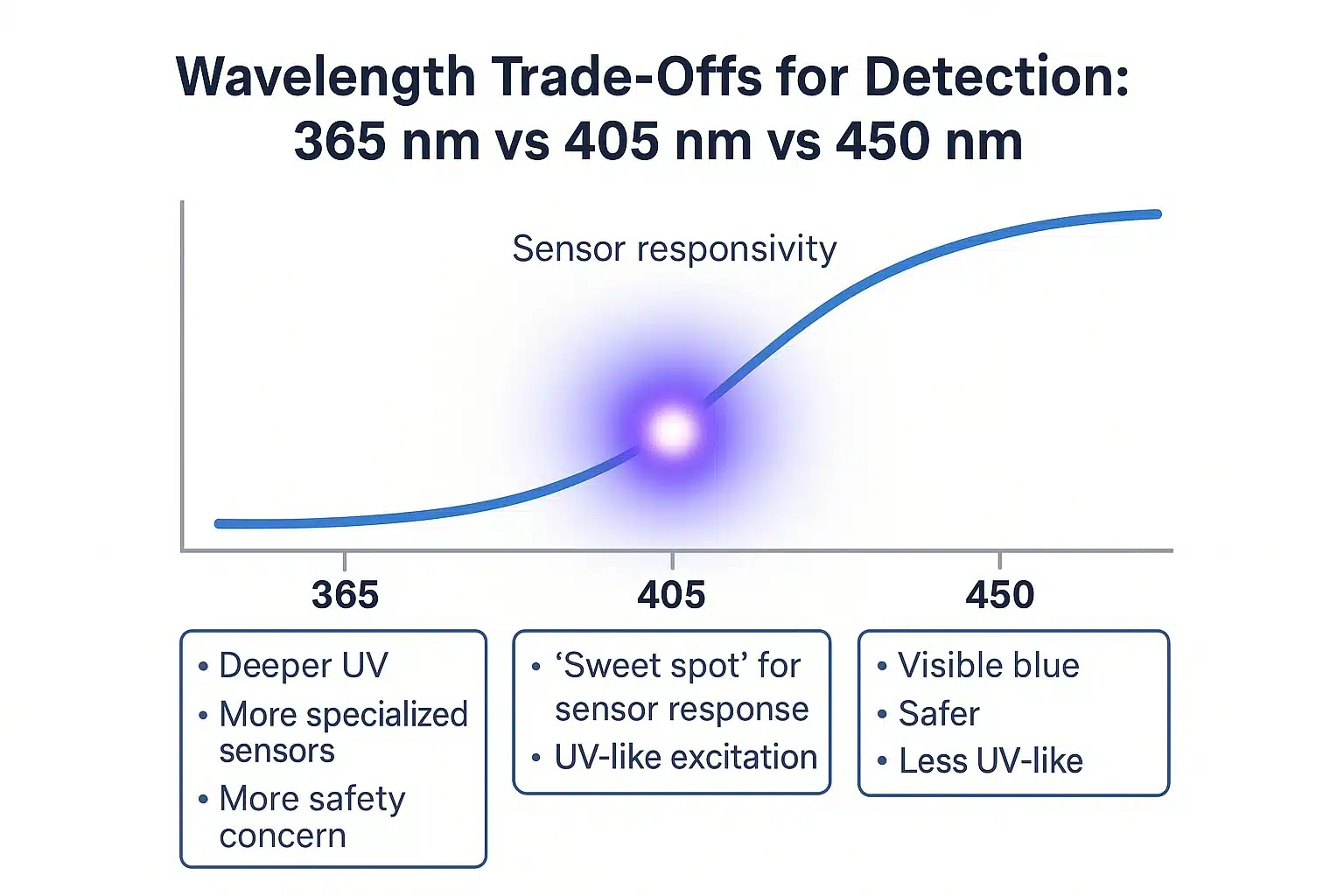
Sensor responsivity increases from UV (365 nm) to violet (405 nm) to visible blue (450 nm), illustrating why 405 nm acts as the practical “sweet spot” between UV excitation strength and detector efficiency.
The 405 nm wavelength offers a balance between deeper UV and visible blue that is ideal for many optical detection tasks. Compared to a 365 nm UV LED, a 405 nm LED provides slightly less energetic photons, but it often excites fluorescence nearly as efficiently while being much easier to detect with standard sensors. Many common fluorophores and substances have absorption bands in the near-UV; in fact, 405 nm light overlaps the Soret band of porphyrin molecules, enabling strong fluorescence excitation in biological samples. At the same time, silicon-based detectors (cameras and photodiodes) are far more responsive at 405 nm than at 365 nm. A typical silicon photodiode might have essentially zero responsivity deep into the UV, whereas it can achieve around 0.28 A/W sensitivity at 405 nm. In practical terms, this means a violet LED source can produce a measurable signal with a regular sensor, whereas a 365 nm source might require specialized UV-sensitive instrumentation. If a material’s excitation curve is at 365 nm, a violet LED often ends up the pragmatic choice. For general visible-light tasks, a blue 450 nm or white LED is safer and more efficient, but when UV excitation or enhanced contrast is required, 405 nm often hits the sweet spot.
For completeness, note that intermediate UV-A options like 385 nm or 395 nm LEDs exist with their own trade-offs. And if true germicidal sterilization is needed, a UV-C LED (~265 nm) would be the appropriate choice, whereas for other wavelength needs such as a 660 nm LED in the red or a SWIR LED in the infrared, entirely different design considerations apply. In summary, 405 nm sits in a sweet spot — it reaches into UV-A enough to excite many targets, yet retains much of the efficiency and ease-of-use of visible LEDs.
Fundamentals of Optical Detection: Irradiance, Photon Flux & Sensor QE
In designing a 405 nm optical detection system, it’s critical to consider irradiance and photon flux delivered to the target. Irradiance (in mW/cm2) describes how much optical power falls on a given area, directly affecting the strength of any fluorescence or reflected signal produced. A higher irradiance of 405 nm light on the sample generally yields a stronger detected signal, up to the point of saturation. Equally important is photon flux – the number of violet photons arriving per second – since fluorescence and photochemical processes depend on photon count. At 405 nm, each photon has about 3.06 eV of energy, so a given optical power corresponds to a very high photon flux. Ensuring high irradiance and sufficient photon flux typically means using a high-output LED and possibly optics to focus or collimate the beam toward the sample.
On the detection side, the sensor’s quantum efficiency (QE) at 405 nm must be accounted for. Most silicon sensors have decent QE in the violet/UV-A range, but some camera sensors include UV-blocking filters that cut off around 400 nm. For maximum sensitivity, those filters may need removal or a UV-sensitive detector (like a UV-enhanced photodiode) should be used. Using a stable, low-noise LED driver (constant-current power supply) is also essential to maintain consistent light output. Any flicker or drift in the LED could introduce noise in the measurement, so a well-regulated LED driver circuit is preferred. In some cases, engineers pulse the 405 nm LED and use lock-in detection to boost the signal-to-noise ratio. By modulating the LED (for example, at 1 kHz) and synchronously detecting the sensor output, one can filter out ambient light. When using such pulsed operation, remember that the duty cycle and average power matter: driving the LED at higher-than-normal currents in short pulses can increase peak irradiance, but the average power must stay within the LED’s thermal limits to avoid overheating. Always check the maximum current rating and thermal specifications – a brief pulse can exceed the datasheet current if the duty cycle is low, but the temperature of the LED junction should be monitored. In summary, deliver enough 405 nm photon flux to excite your target, use a detector with good responsivity at that wavelength, and control the LED output stability either via constant current or synchronized pulsing for optimal detection performance.
Applications in Fluorescence, Microscopy, Machine Vision & Sensor Illumination
The 405 nm violet LED has become a workhorse in various fluorescence and optical sensing applications. In life science and microscopy, high-power 405 nm LED light sources are used to excite fluorescent dyes and proteins in samples. For instance, modern fluorescence microscopes often include a 405 nm LED illumination module as a replacement for traditional mercury lamps or lasers. Thorlabs, for example, offers a dedicated 405 nm LED for microscopy that delivers over 1.6 W of violet output for fluorescence excitation. This allows imaging of common stains (like DAPI, which has an excitation peak around 360–405 nm) and other fluorophores with a stable, mercury-free light source. The LED’s narrow bandwidth and instant on/off control make it ideal for techniques like epifluorescence and confocal microscopy, where precise wavelength and timing are important. Additionally, because 405 nm is just on the edge of visible light, microscope operators can often see a dim violet glow when the beam is on a sample, providing feedback without significantly adding background light.
In industrial machine vision and quality inspection, 405 nm LEDs are used to reveal features that are invisible under normal illumination. Many automated inspection systems include violet LED lighting to cause certain materials to fluoresce or to enhance contrast of UV-reactive markings. For example, a manufacturer might apply a UV-sensitive adhesive or ink to a product; under a 405 nm LED inspection lamp, this coating will fluoresce brightly, allowing cameras or sensors to verify its presence and uniformity. Similarly, contaminants or residues on surfaces can often be detected by the fluorescence they emit under near-UV illumination. To cover wide conveyor belts or large areas, multiple LEDs may be arranged in an LED array or bar light, paired with diffusers or lenses to ensure uniform, high output coverage. The optics must be chosen carefully – acrylic or polycarbonate lenses will block much of the UV light, so glass or fused silica optics are preferred to transmit the 405 nm light efficiently. By integrating the right optics, a 405 nm LED lighting system can produce a uniform, intense illumination field tailored to machine vision cameras. Several lighting manufacturers provide off-the-shelf 405 nm LED fixtures (ring lights, line lights, etc.) for this purpose, making it straightforward to add violet illumination to an inspection setup.
Beyond machine vision, 405 nm serves in various sensor illumination modules. Environmental and biomedical sensors often incorporate a 405 nm LED to induce fluorescence or absorbance changes in a sample. For instance, a portable water quality sensor might shine a 405 nm beam through a sample and use a photodiode to detect fluorescence from organic compounds, indicating contamination levels. In gas sensing, certain aromatic hydrocarbons can be excited with 405 nm light to produce identifiable optical signatures. Because these LEDs are compact and can run on low-voltage drivers (often 5V or 12V modules), it’s practical to embed them into handheld instruments and sensor nodes. The near-UV output provides the necessary optical power for detection reactions without the bulk or fragility of a UV lamp. In all these cases, the inclusion of feedback photodiodes for monitoring the LED output can further improve measurement reliability, as the system can calibrate out any LED intensity drift over time by referencing the built-in monitor photodiodes.
Packaging & Thermal Design for High-Power 405 nm LEDs (COB, SMBB, EDC)
Driving a 405 nm LED to high optical outputs requires careful attention to packaging and thermal management. High-power LEDs generate significant heat, and this is especially true for UV/violet LEDs where efficiency (light out vs. electrical in) is a bit lower than for some visible LEDs. To prevent thermal runaway and performance degradation, the LED package must efficiently conduct heat away from the junction (the diode’s active region) to an external heat sink. One common approach is the COB (Chip-on-Board) package, where multiple LED chips are mounted directly on a thermally conductive substrate (often aluminum or ceramic) and encapsulated together. By spreading several violet LED chips across one board, a COB module can achieve very high optical power (dozens of watts) in a single component. For example, a COB array might combine enough emitters to reach a 60W output, suitable for a large UV curing fixture. These high-power assemblies simplify the optical design (one large source vs. many small ones) but demand robust cooling – often an aluminum core board and external heatsink with fan are used to dissipate heat.
For more compact high-power devices, specialized surface-mount packages are available. The High-power SMBB series (a 5.0 × 5.0 mm ceramic package) is an example of a multi-chip SMD LED designed for maximum output. An SMBB package typically integrates one to three violet LED chips onto a copper heat spreader inside a ceramic body, providing a low thermal resistance path. Likewise, the High-power EDC series (a 3.5 × 3.5 mm package) implements similar power handling in a smaller footprint. These advanced packages allow engineers to drive the LED at high current – for instance, 500 mA or more per chip – without overheating, as long as the module is mounted to a proper heatsink. The LED chip(s) sit on a metallized thermal pad that must be soldered or thermally bonded to a PCB or heat sink. It is crucial to use thermally conductive interface materials (thermal grease or pads) and keep mounting surfaces flat to ensure good heat transfer. A high-power 405 nm LED’s performance and lifespan depend directly on how effectively you keep its junction temperature below the rated maximum (often around 100–120 °C). In practice, that means a combination of heat spreading (e.g., copper planes on a PCB), heat sinking (e.g., attached finned heatsink or metal housing), and possibly active cooling.
Proper thermal management is not just about avoiding immediate failure; it also maintains the optical output over time. If the LED runs cooler, it will suffer slower optical degradation, meaning more output over its lifetime. Manufacturers often specify in the datasheet how output decreases per degree rise (e.g., % per °C) and provide derating curves. Note that the temperature of the LED case will be much lower than the actual junction temperature, so always use the given thermal resistance values to estimate the true junction temperature under load.
Optics & Integration: Beam Shaping and Uniform Illumination
Integrating a 405 nm LED into an optical system often requires adding optics to shape and direct the light. By default, most high-power LED chips emit in a lambertian pattern (roughly a 120° wide glow). For many fluorescence and sensing setups, you’ll want to collect and focus this light to increase irradiance on the target. Common solutions include using collimator lenses, reflector cups, or optical fiber coupling. Because 405 nm lies in the near-UV, one must choose lens materials that transmit this wavelength well – standard optical glass (borosilicate or BK7) typically works for 405 nm, but some plastics or cheap glass may absorb a portion of the UV. Quartz or UV-grade fused silica lenses offer excellent transmission at 405 nm and below, though they are more expensive. Simple plano-convex lenses can focus a high-power LED down to a spot to achieve high irradiance, while engineered TIR (total internal reflection) optics or reflectors can also be used to collimate the LED light. If a very uniform field is needed (for example, illuminating a sensor array or a camera field of view evenly), engineers might employ diffusers or light pipes. An integrating sphere or a homogenizing light guide can take the naturally non-uniform LED output and distribute it evenly, at the cost of some optical power loss.
Certain applications illustrate these optical integration techniques well. In a DLP-based UV projector for lithography or 3D printing, a 405 nm high-power LED is coupled through lenses into a digital micromirror device – the optics are designed to provide a uniform, intense illumination on the DLP chip so that when it projects an image, the resin or substrate receives an even dose of violet light. This often involves a fly’s eye integrator or light tunnel to homogenize the LED output before it reaches the micromirror array. On the other hand, for a straightforward machine vision task like reading invisible ink markings, one might simply use a narrow-bandpass filter on the camera and a set of 405 nm LED spotlights with diffuser film to flood the area with violet light. The goal is to maximize the signal (fluorescent glow or reflected contrast) while minimizing glare and hotspots. Practical considerations include mounting and alignment of the optics with respect to the LED – for instance, many high-power LED packages come with an optional ball lens or window. If not, external optics must be positioned at the correct distance (taking into account the LED chip size and emission cone). Mechanical integration may involve adjustable lens holders or fiber couplers. Ultimately, careful optic selection ensures the 405 nm light is delivered where and how it’s needed – whether as a focused beam, a structured pattern, or a diffuse illumination – with minimal losses.
Measurement & QA: Photodiodes, Radiometry, and Calibration
When deploying 405 nm LEDs in critical applications, it’s important to verify and maintain their optical output over time. During system development, an optical measurement of the LED’s output (spectrum and power) should be performed using a calibrated spectroradiometer or photometer. This provides a baseline of the LED’s actual irradiance and wavelength, rather than just relying on the catalog values. In production or field use, simpler methods can be employed: for example, a reference photodiode sensor can be installed to continuously monitor the LED’s output intensity. Photodiodes designed for UV/VIS detection will produce a current proportional to the 405 nm light intensity, which can be read by a microcontroller to check if the LED output is within the expected range. According to industry practice, these monitor diodes can be used in a feedback loop – if the LED output starts to drop (due to LED aging or temperature changes), the system could incrementally raise the drive current to compensate, or flag a maintenance alert once the output falls below a threshold.
For quality assurance, consistency and traceability are key. Any photodiodes or radiometers used should be calibrated for 405 nm so their readings are accurate. In operation, periodic checks of the LED output (using a UVA radiometer or the built-in monitor diode) help ensure the system stays within spec. Over time, the LED’s optical power will slowly decline, so tracking its output vs. runtime lets you decide when to recalibrate or replace the LED module (for instance, at the L70 point). By integrating monitoring and regular calibration checks, you can guarantee that a 405 nm LED-based system continues to perform to specifications throughout its service life.
Safety & Compliance: Eye Protection and Violet Light Hazards
While 405 nm LEDs are much “safer” than deep ultraviolet sources, they still pose certain hazards at high power. Violet light at 405 nm is on the edge of the visible spectrum, so it can enter the eye and focus on the retina, potentially causing a blue-light hazard. Direct exposure to an intense 405 nm beam can damage eyesight over time or cause acute visual discomfort. Therefore, appropriate eye protection is a must when working around high-irradiance 405 nm LED systems. Operators should wear UV safety glasses that are rated to block violet/UV-A wavelengths for eye protection, especially during alignment or maintenance when one might inadvertently glance into the LED. Additionally, 405 nm illumination can cause fluorescent materials in the environment to glow, which might lead to distractions or mild skin exposure, though the skin hazard from 405 nm is negligible compared to true UV. According to discussions of antibacterial violet lighting, 405 nm at recommended dosages is not harmful to human skin and is comparable to naturally occurring visible-violet exposure.
Nonetheless, any high-power LED system should undergo a photobiological safety evaluation per standards like IEC 62471. This standard classifies lamps and LEDs into risk groups (Exempt, RG1, RG2, RG3) based on their emission and potential hazards. Many 405 nm LED products meet thresholds for continuous, unrestricted use around people (often Exempt or RG1), but if you concentrate the light (for example, through optics) to very high intensities, it could become RG2 (moderate risk). Manufacturers should provide hazard distance information – e.g., the distance beyond which the light is safe for indefinite viewing. In a machine integration, it’s wise to include interlocks or shielding: for example, enclose the UV LED such that operators cannot stare directly into it, and use diffused illumination rather than a naked LED die output when possible. Also consider labeling the equipment with warnings like “Caution: UV-A LED – Avoid Eye Exposure,” even if the light appears mostly violet. By following laser safety analogs (like providing goggles and light-tight enclosures) and adhering to IEC/ANSI photobiological safety guidelines, engineers can ensure that using 405 nm LEDs for fluorescence and detection does not introduce health risks. The bottom line: treat high-intensity violet LEDs with respect – use proper shielding, limit direct viewing, and follow compliance standards – and you can safely harness their benefits. For reference on consumer-facing violet products, see this note on risk-group classifications and usage.
System Design Examples & Case Studies
- Machine Vision Fluorescence Inspection: An electronics manufacturer prints invisible UV fluorescent markings on parts for quality tracking. A custom station uses a bank of 405 nm LED lights above a conveyor to excite these markings, which then fluoresce bright green against a dark background for a camera to detect. By using diffused high output LED panels, the system achieves uniform coverage across the field of view.
- SLA/DLP 3D Printer Resin Curing: Many resin 3D printers (stereolithography and DLP types) use a 405nm LED curing light (often marketed as a UV curing light 405nm) to solidify photopolymer resin layer by layer. These printers typically employ either an array of 405nm LEDs or a single high-power LED combined with a DLP projector to expose each resin layer with a patterned violet image. This wavelength is ideal because common 3D printer resins are formulated to absorb around 405 nm, allowing fast curing. The LED light source is compact and energy-efficient, producing far less heat than a mercury UV lamp while still curing the resin quickly.
- Portable Fluorescence Analyzer: A handheld diagnostic device uses a 405 nm LED and a photodiode sensor to perform fluorescence assays on fluid samples. The violet LED excites a dye in the sample, and the photodiode measures the emitted green light to determine the analyte’s concentration. The design uses a single 1W 405 nm LED driven by a low-noise LED driver and powered by a rechargeable 5V battery. Thanks to proper thermal management, the LED provides stable output over repeated tests, making the device a reliable portable fluorimeter for field use.
Sourcing & Reliability: Binning, Lifetime and Supply Chain
When selecting a 405 nm LED for your project, it’s important to consider the sourcing and binning options offered by manufacturers. LEDs are typically binned by wavelength and radiant flux. For a violet LED, this means you may be able to choose a bin centered at, say, 400 nm, 405 nm, or 410 nm, with a tolerance of a few nanometers. Selecting a tighter wavelength bin (if available) ensures consistency, especially crucial if you use multiple LEDs and need them to match for uniform fluorescence excitation. Output power binning is also relevant – some suppliers bin high-power LEDs by optical output (mW) at a given current. If your application requires maximum intensity, you might opt for the highest bin, although that can come with a price premium. It’s wise to obtain a few sample LEDs from the same bin and test them in your system, as real-world performance can vary slightly even within the bin range. Additionally, check the manufacturer’s catalog or datasheets for any notes on bin availability; certain bins (like exactly 405 nm) might be produced in smaller quantities or have longer lead times.
Reliability and lifetime are another key part of the equation. A well-made 405 nm LED operated within spec can offer a long service life, but “long” in the context of UV LEDs might be on the order of tens of thousands of hours, not the 100,000+ hours sometimes quoted for visible LEDs. The industry standard for lifetime is usually given as L70 (the time to 70% output remaining). High-power UV LEDs often advertise L70 lifetimes in the 10,000–20,000 hour range at rated conditions, though this can be extended by driving them at a lower current or keeping them cooler. For instance, one supplier’s 405 nm LED had a >10,000 hour typical lifetime when driven at full power, but by running it at 80% of max current and with aggressive cooling, users report getting significantly longer useful life. It’s also worth looking at the device’s Mean Time To Failure (MTTF) or other reliability metrics if provided. Unlike incandescent lamps that tend to “burn out,” LEDs typically fade gradually (lumen depreciation) or fail due to packaging issues (e.g., cracked bond wires, delamination) often exacerbated by heat. A robust violet LED from a reputable manufacturer will have undergone accelerated life testing to ensure it can handle thermal cycling and long-term operation. Check for any notes about sulfur resistance or UV-specific degradation modes (since shorter wavelengths can sometimes yellow plastics or cause lens aging).
From a supply chain perspective, 405 nm LEDs are in healthy demand and are produced by multiple LED makers, which helps with availability and second-sourcing. This wavelength is popular for applications from UV curing to analytical instruments, so you’ll find it in the catalogs of specialized UV LED manufacturers as well as major LED companies. However, do be mindful of generational improvements: LED efficacy (mW per input watt) for 405 nm has been improving over the years, so newer product lines might offer higher output or better efficiency. If you start a design with one LED model and plan for production years down the line, ensure that exact model will still be available or that there’s a pin-compatible successor. It’s not uncommon for LED vendors to release improved “next-gen” versions (with a slight flux boost or tighter binning) as die technology advances. Establishing a relationship with the supplier or a distributor can help you stay informed about product roadmaps. Lastly, always obtain the LEDs through authorized channels to avoid substandard or counterfeit components – the UV LED market is niche, and you want to trust that the parts you get indeed meet the published specs.
Selection Checklist & Next Steps
Before finalizing the use of a 405 nm LED in your design, review the following checklist to ensure all key factors have been addressed:
- Wavelength Requirements: Confirm that 405 nm is the optimal wavelength for your application’s fluorescence or sensor response. If tighter UV or different spectra are needed, evaluate other LED options.
- Output Power & Irradiance: Calculate the optical power (mW) and irradiance needed. Choose a package (e.g., single high-power LED vs. COB array) that can deliver the required output with some safety margin.
- Thermal Management: Design a heatsink and possibly active cooling to keep the LED junction well below its maximum temperature. Use thermal interface materials and consider real-time temperature monitoring for high-duty applications.
- Drive Electronics: Select a constant-current LED driver or appropriate power supply. Ensure it can supply the necessary current (e.g., 500 mA, 1 A, etc.) and has low ripple to avoid noise in optical measurements. Implement PWM or pulse control if needed, but stay within safe duty cycles.
- Optics and Beam Shaping: Choose lenses, reflectors, or diffusers suitable for 405 nm. Ensure they are made of UV-transmitting materials. Align the optical components to achieve the desired spot size or uniform illumination for your sensor or sample.
- Sensor and Filters: Use detectors (camera, photodiode) that are sensitive at 405 nm or remove any UV blocking filters. Incorporate emission filters in fluorescence setups so that only the emitted light (not the 405 nm excitation) reaches the detector.
- Safety Measures: Add necessary shielding or interlocks to prevent direct eye exposure to the 405 nm light. Provide UV-rated safety goggles to personnel and label the system with appropriate warnings about violet/UV light.
- Reliability & Maintenance: Check the LED’s lifetime and plan for maintenance or replacement after the expected L70 period. If the process is critical, consider using a monitoring photodiode and designing redundancy or easy swap of the LED module.
- Sourcing: Secure parts from reputable suppliers and note the exact bin or part number for consistency. Have a second source or backup plan in case of procurement issues, especially for specialized UV LEDs.
By following the above checklist, engineers can confidently integrate a 405 nm LED into their fluorescence detection or optical sensing system. For a broader overview of LED wavelength considerations across the spectrum, you can refer to our upcoming LED Wavelength Guide. If you are exploring other parts of the spectrum, we also cover topics like deep UV-C LEDs and infrared emitters in separate articles. Ultimately, understanding the nuances of this violet wavelength enables you to leverage it to its fullest potential in your design. And when you’re ready to get hands-on, be sure to consult the product documentation for the specific LED you’ve chosen. We invite you to learn more about our 405 nm LED offerings – technical details can be found in the datasheet below.