In industrial inspection and machine vision systems, high-power 450nm LED sources have become a key element for providing intense blue illumination. This “royal blue” wavelength sits at the cusp of the visible spectrum between violet and green, offering high-energy photons for enhanced contrast without veering into ultraviolet UV light. These high power LEDs provide intense output while maintaining high electrical-to-optical efficiency, making them ideal for illuminating detailed inspections. However, engineering teams must balance raw intensity against factors like heat, lifetime, and the sensitivity of detectors. This article explores how 450 nm LEDs achieve bright blue lighting for inspection tasks, the trade-offs between intensity and efficiency, and practical design considerations for anyone selecting a blue LED solution for industrial use.
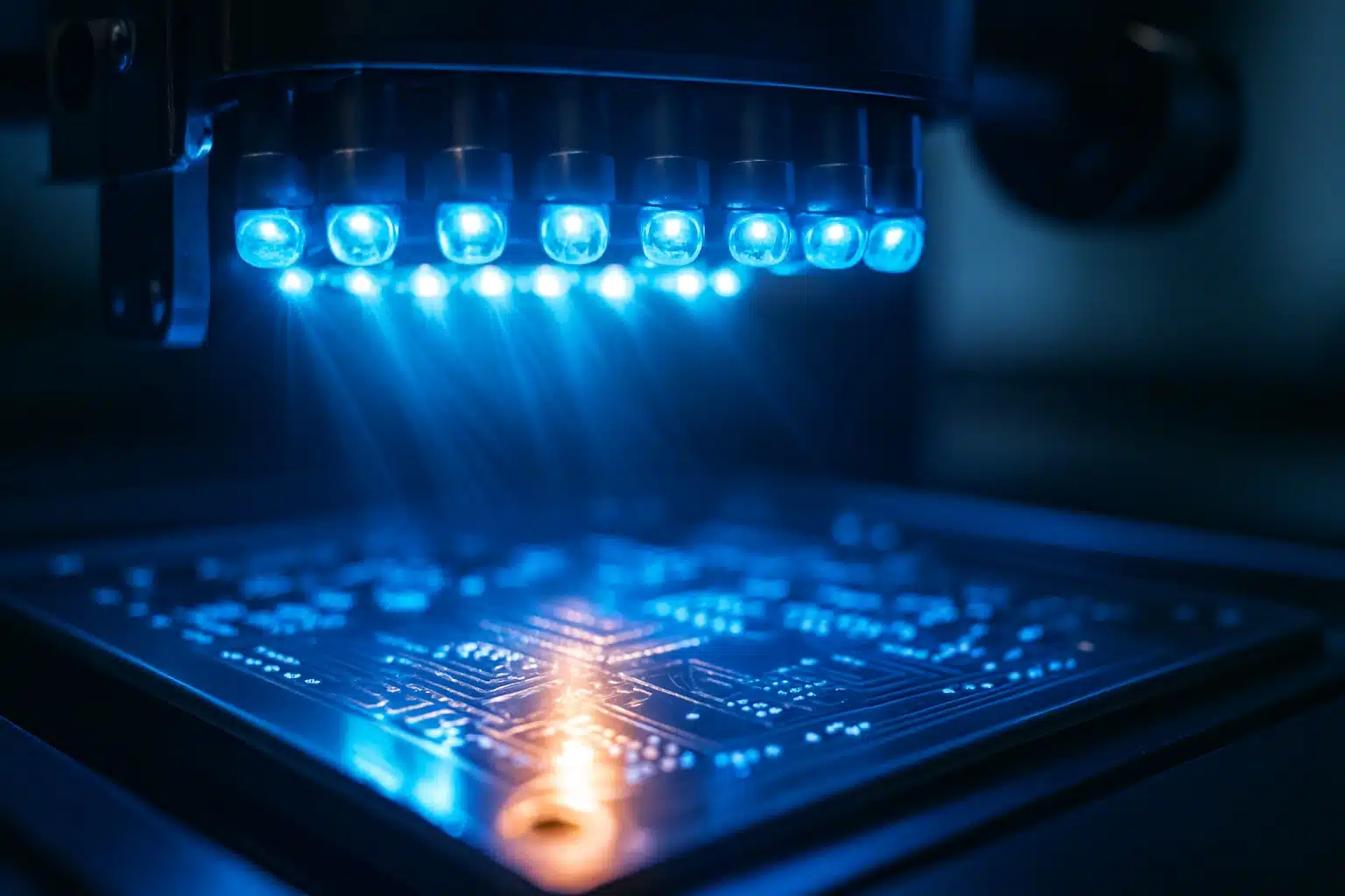
Array of Blue LEDs Inspecting a PCB
What defines a 450 nm LED wavelength?
A 450 nm LED is a light emitting diode engineered to emit light with a peak wavelength around 450 nanometers (nm), squarely in the blue portion of the spectrum. Often called a “royal blue” LED, its emitted light appears as a deep blue color. The LED chip is typically made from indium gallium nitride (InGaN), a material whose band gap is tuned to produce photons in this 450 nm range. Unlike a laser diode module that emits a single wavelength, an LED has a spectral bandwidth – the 450 nm class LED might have a full width at half maximum (FWHM) of about 20–30 nm, meaning it outputs a narrow band of blue wavelengths rather than a perfect monochromatic line. In other words, a 450 nm LED emits light centered at 450 nm with some spread on either side (a quasi-monochromatic spectrum).
This wavelength is at the border between visible violet and the rest of the visible blue range. For context, 405nm is considered a near-UV violet LED (borderline UV light), while a 660nm LED would be a deep red emitter. Compared to a 405 nm UV-violet source, a 450 nm blue LED is safely within the visible spectrum, which simplifies its use in standard optics (lenses don’t need special UV coatings and there is less risk of UV hazards). Compared to a red 660 nm LED, the 450 nm LED photons carry higher energy, which can improve the excitation of certain materials or fluorescent markings during inspection. (Each photon at 450 nm has about 2.75 eV of energy, versus ~1.88 eV for 660 nm.) The high photon energy is one reason blue LEDs are used as the “pump” in white light LEDs – a blue LED coated with phosphor can generate broad-spectrum white illumination. In industrial settings, a pure 450 nm LED provides a saturated blue illumination that can be crucial for certain machine vision tasks. For an overview of how 450 nm fits into the broader LED spectrum, you can refer to our LED wavelength guide (placeholder link) and explore related wavelengths like 365 nm UV LEDs (placeholder link), 405 nm violet (placeholder link), or 660 nm red LEDs (placeholder link).
It’s worth noting that 450 nm falls in the middle of the visible LED range (400–800 nm) that Tech-LED offers, including options for 365nm and 450nm blue LEDs. By contrast, shorter-wavelength LEDs in the UV range (down to 365 nm) or longer-wavelength IR LEDs (near-infrared) and SWIR LEDs move out of the visible spectrum. The 450 nm “blue” is distinct because it borders those transitions: it’s visible light, yet energetic enough to overlap with some tasks that used to require UV. This unique position makes 450 nm a popular choice for applications that need high-energy visible light.
Why choose 450 nm vs 405 nm or 660 nm?
Selecting an LED wavelength for a vision system depends on the optical properties of the target and sensor. A natural question is: why use a blue 450 nm LED instead of a 405 nm near-UV or a 660 nm red LED? One reason is the spectral sensitivity of cameras and the human eye. Silicon-based detectors (CCD/CMOS cameras or photodiodes) typically have decent quantum efficiency at 450 nm, though not as high as in the green-red range, as shown in quantum efficiency curves published by Hamamatsu. A standard front-illuminated machine vision sensor is more sensitive to green and red wavelengths than to blue, because blue wavelengths are partly absorbed in the sensor’s shallow structures, a behavior also documented in Hamamatsu’s sensor structure analysis. However, modern sensors still detect blue sufficiently well, and using a bright blue LED can produce ample signal. Meanwhile, human eye sensitivity is much lower at 450 nm than at longer wavelengths. In fact, monochromatic light at 450 nm has a theoretical luminous efficacy of only about 26 lumens per watt, versus 683 lm/W at the eye’s peak 555 nm, according to DOE luminous efficacy reference data. In practical terms, a deep blue lamp will appear dimmer to a human observer than a red or white lamp of the same radiant power. But machine vision systems care about photons, not perceived brightness – a camera or detector can be calibrated to the blue output. So if your system is primarily camera-based, the low luminous output (in lumens) of blue light is not a drawback, and you can leverage the high radiometric intensity of a 450 nm emitter.
Wavelength also affects contrast. Blue illumination interacts with objects differently than red or infrared LED illumination. For example, if you need to inspect an object with red markings or a red surface, shining a blue LED will make those red features appear almost black to a monochrome camera (because red surfaces absorb blue light). According to a machine vision lighting guide by Keyence, a blue LED can be optimal when trying to detect a red-colored target, as the complementary color effect yields strong contrast. On the other hand, red light can penetrate deeper or scatter less in certain materials. Keyence’s guide also notes that reading print through a translucent film showed higher contrast under red 660 nm illumination than blue, because the longer wavelength had higher transmittance and lower scattering in that medium, as illustrated in their wavelength comparison examples. Thus, 450 nm might be chosen for its ability to enhance contrast for certain colors or surface features, whereas 660 nm might be better if you need to see through an overlay or reduce scattering.
Another consideration is fluorescence and optical brighteners. Many inspection scenarios use blue light to excite fluorescence in materials or dyes. A 450 nm LED, while not as energetic as UV, can still cause certain compounds (like optical brighteners in fabrics or security marks) to emit visible glow, aiding detection. If ultraviolet excitation is needed, one might consider a true UV LED (e.g., 365 nm or 405 nm), but those come with more safety precautions and often lower efficiency. Blue at 450 nm is a balance – it’s energetic enough to interact strongly (for example, it can induce fluorescence in some inks or contaminants), yet it’s visible light so it can be safer and easier to work with than UV. Ultimately, choosing between 405 nm, 450 nm, 660 nm or other wavelengths requires evaluating the sensor response, the target material properties, and the lighting environment. Many advanced inspection systems even use multiple wavelengths sequentially: for instance, a UV or blue illumination to highlight one feature and a red or IR illumination to highlight another.
Blue LED intensity vs efficiency: what matters for inspection lighting?
When designing an inspection light source, engineers often face a trade-off between maximizing intensity and maintaining efficiency. “Intensity” here refers to the optical output (radiant flux, measured in milliwatts (mW)), while “efficiency” refers to how effectively the LED converts electrical power into light (often given as a percentage or lumens/Watt for visible light sources). At 450 nm, the distinction between radiant and luminous output is important – a blue LED’s light output might be high in radiometric terms (mW of optical power) even if the luminous output in lumens is low due to the eye’s sensitivity curve. In machine vision, it’s the radiometric output (photon flux) that matters for the camera exposure.
The good news is that modern 450nm LEDs are among the most efficient emitters available. Research has shown that blue LEDs can achieve around 93% external quantum efficiency under optimal conditions – meaning almost all electrons contribute to emitting light. In practical terms, high-power royal blue LED chips might reach 50–60% wall-plug efficiency in well-designed systems, far outperforming older LED technology. This high efficacy is one reason blue LEDs serve as the “engine” in many LED lighting solutions (e.g., phosphor-converted white LEDs rely on an efficient blue emitter). However, efficiency tends to drop as you push the LED to higher drive currents or higher junction temperatures. This phenomenon, known as “efficiency droop,” means that running an LED at, say, twice the current might not give twice the light output – some energy is lost as heat at high injection levels.
For inspection lighting, this requires balancing continuous output and lifetime. If an application demands maximum intensity – for example, freezing motion with a very bright strobe – an engineer might overdrive a 450 nm LED in short pulses. Pulsing an LED (with a laser diode driver style constant-current pulse circuit) can deliver higher peak brightness in flash mode without overheating the junction, as long as the duty cycle is low. In continuous wave operation (CW mode), one must respect the LED’s thermal limits. The higher the forward current, the more heat and the lower the efficiency, so there is a diminishing return on pumping in more current beyond a certain point. Thermal management (discussed later) is crucial to maintain both intensity and efficiency over time.
An important aspect is safety and eye considerations. Blue light is sometimes associated with photobiological risk (the so-called “blue light hazard”), but in properly designed inspection lighting, exposure levels are usually controlled. Standards like IEC 62471 categorize risk groups for lamps; most small high-power LEDs, when used with appropriate diffusers or at working distances, can be kept in safe exposure ranges. In fact, an analysis by the Illuminating Engineering Society noted that at typical indoor lighting levels, the amount of blue light from LED sources is dwarfed by what we receive from natural sunlight – indirect daylight can expose us to 27 times more blue energy in the 400–490 nm band than a blue LED lighting system would. Nonetheless, it’s wise to avoid staring into any intense LED. From an engineering perspective, “efficiency” in this context also means using just enough optical power to get the job done (for good image contrast) without creating unnecessary glare or hazard. Thus, the goal is to harness the excellent efficacy of 450 nm LEDs to get strong illumination (whether measured in lumens or mW) while minimizing wasted energy as heat and avoiding operating regimes that drastically shorten the LED’s lifespan.
Spectral characteristics of 450 nm blue LEDs
The spectral output of a 450 nm blue LED is a concentrated band of blue wavelengths. Typically, the dominant wavelength will be around 450 nm with a spectral width (FWHM) on the order of tens of nanometers. For instance, an LED specified as 450 nm might actually have a peak at 450 nm and emit significant light from roughly 430 nm to 470 nm. This relatively narrow spectrum is extremely useful in machine vision because it means the light source is essentially monochromatic blue. You don’t need filters to get a pure color – unlike a white lamp where you’d have to filter out everything but blue. The narrow spectrum also pairs well with optical filters on the camera side: a bandpass filter centered at 450 nm (with maybe a 40 nm bandwidth) can block ambient light or other wavelengths, ensuring that only the LED’s illumination is captured. This can boost contrast and stability in an inspection system.
The angular output of a bare LED chip (with no secondary optics) is typically a Lambertian distribution, which for a flat LED chip equates to a roughly 120° wide viewing angle (the LED emits light in a broad cone). Many high-power blue LEDs are packaged with primary lenses that narrow this beam – common lens packages yield viewing angles like 30°, 60°, or 90° to provide a more intense, directed beam. For example, a blue 3535 SMD LED with a dome lens might have a 60° viewing angle, concentrating the light. Additional optics can further shape the beam: using external lenses or reflectors to collimate or diffuse the light as needed. In applications that require uniform illumination over a field (say a line-scan camera inspecting a conveyor), engineers often use diffuser films or specific lens arrays to distribute the 450 nm light evenly.
It’s also worth noting how 450 nm spectra integrate into multi-wavelength systems. In a white LED, the blue LED’s spectrum excites a yellow phosphor to produce broad “white” light. That’s why white LEDs have a residual blue peak around 450 nm plus a wide phosphor emission. In multi-color LED systems, a 450 nm emitter might be combined with other colors (for instance, red and green LEDs) to produce a tunable or broad spectrum illumination. In such cases, each LED’s spectral contribution can be independently controlled. Blue LEDs also find use in fluorescence microscopy and imaging: 450 nm is a common excitation band for certain fluorescent dyes. In those contexts, the narrow spectral output ensures that emitted fluorescence can be cleanly separated from the illumination light by using optical filters. The key spectral takeaway is that a 450 nm LED provides a pure, intense blue light with minimal out-of-band emission – a highly controllable light source for precision imaging.
For completeness, remember that an LED’s dominant wavelength can shift slightly with temperature and drive current. A 450 nm LED might peak at 450 nm at 25°C, but if it heats up significantly, the peak could red-shift by a few nanometers. Manufacturers will specify this typically (e.g., a shift of ~0.05 nm/°C). It’s a minor consideration but in extremely sensitive systems it might matter for calibration. In general, though, the spectral stability of these devices is good enough for most industrial uses, and any small shifts don’t change the overall blue nature of the light.
High-power 450nm LEDs: packages, SMD, and COB options
Driving a blue LED to high optical powers requires the right packaging, especially for 450nm blue models. Standard indicator LEDs (like the little 3mm or 5mm epoxy-encapsulated lamps) cannot handle the currents needed for intense illumination. High-power 450 nm LEDs come in packages designed for heat dissipation and optical output. These include surface-mount power LEDs (often in SMD LED packages on ceramic or metal-core boards), Chip-on-Board (COB) modules, and specialty mount packages. For instance, you can find 450 nm “star” LEDs where the LED die is mounted on a metal-core PCB star board for easy bolting to a heat sink. In Tech-LED’s lineup, there are high-power surface-mount packages like the SMBB series and EDC series, which are designed to handle higher currents while efficiently removing heat. These packages often use a ceramic base or thermal pad that you solder onto a circuit board so that the heat can flow into a heat sink, resulting in essentially a board mounted LED solution. By spreading multiple LED chips out (as in a multi-die COB array) or using packages with low thermal resistance, designers can achieve high light output levels without overheating the junctions.
The choice of package also affects the optical format. A COB might integrate dozens of blue LED chips on one substrate to act as a single intense light source (for example, a COB might be used in a high-intensity spotlight or a curing lamp). COBs offer a very high LED chip density, which gives a compact powerful source, but they concentrate heat and can have slightly lower efficacies than discrete LEDs because of heat concentration (the efficiency per chip can drop a bit due to mutual heating, as noted in a white paper comparing COB vs POB architectures, particularly in the context of 450nm blue LED performance.). SMD LED packages, on the other hand, can be spaced out or individually lensed, providing flexibility. There are also through-hole high-power LEDs in metal can packages (like those emitting at 450nm blue) for enhanced durability. TO-18 or TO-5 headers) used in some applications for their stability and easy lens attachment, but these are more common in laser diodes or IR LEDs than in visible blue LEDs.
When mounting high-power blue LED packages, you must consider the mechanical and electrical integration. Ensure the anode and cathode are correctly oriented and that the PCB footprint matches the package. Use the recommended thermal via or pad patterns to draw heat away from the LED. Also, note if the LED package has an isolated heat pad or if one of the electrodes is the thermal pad. Many high-power LEDs have the cathode pad also serving as the thermal path. Proper mounting with solder paste reflow onto a copper plane or attaching the LED to a heat sink with thermal compound (in the case of COB modules) is crucial. A poorly mounted LED will quickly overheat at high forward current. In summary, 450 nm LEDs are available in everything from tiny SMD form factors to large COB assemblies – picking the right one involves trading off ease of use, intensity, and thermal management needs.
Thermal management for high-output blue LEDs
Thermal management is arguably the most critical aspect of using high-power LEDs. For a 450 nm LED driven at hundreds of mA or several watts of input, a significant portion of energy still turns into heat (even at 50% efficiency, half the power is heat). Excess heat raises the LED’s junction temperature, which can reduce light output, shift the wavelength, and accelerate device aging. Each LED will have a maximum junction temperature (often around 120°C) specified by the manufacturer. In practice, keeping the junction much lower – say below 80°C – is advisable for long-term reliability (this is often related to achieving the typical 50,000 hour L70 lifetime).
Effective thermal design starts with the LED package selection (as discussed) and continues with the heat sink or cooling strategy. A metal-core circuit board (MCPCB) is commonly used as the base for mounting high-power LED modules; this MCPCB is then mounted to a chassis or a finned heat sink. Thermal interface materials (pads or paste) should be used between the MCPCB and the heat sink to ensure good conduction. The goal is to maintain a low thermal resistance path from the LED junction to the ambient air. In some high-power cases (e.g., a 12W multi-die 450 nm LED array), even active cooling with a fan or liquid might be necessary. In many machine vision applications, though, passive cooling with a decent heat sink suffices.
What are the consequences of poor thermal management on a blue LED? Firstly, the light output (flux) decreases as junction temperature rises – a rough figure is that you lose some fraction of a percent of light output per degree Celsius increase (e.g., ~0.2–0.3%/°C for many LEDs). Over-driving an LED without proper heat sinking can easily heat the junction by tens of degrees, robbing you of 10–20% of the light and potentially pushing the device into failure. Secondly, the wavelength will drift slightly (higher temperature means a longer peak wavelength, i.e., a more red-shifted output, though only by a few nm). Thirdly, high temperatures exacerbate efficiency droop and can permanently reduce the LED’s efficiency over time by causing materials or contacts to degrade. In extreme cases, insufficient cooling will cause the LED chip or bond wires to overheat and fail outright.
To manage heat, always operate within the LED’s specified drive current unless you have characterized a pulsed overdrive scenario. Ensure that the ambient environment is considered – if the LED is in an enclosure or under other hot equipment, the temperature rise could be more significant. Using a temperature sensor or even the LED’s forward voltage (which drops as temperature rises) as a crude thermometer can help in sophisticated designs to monitor junction conditions. In summary, maximizing the benefits of a high-power 450 nm LED requires treating thermal design as seriously as optical design: the brightest LED solution is only achieved when the LED is kept cool enough to run efficiently.
Optics and beam shaping for inspection and machine vision
Optical control is the other side of the coin for effective inspection lighting. A raw blue LED die will emit a broad, somewhat Lambertian beam, but in machine vision we often need to shape this light. One common approach is adding collimating lenses to produce a tighter beam or to focus the light on a specific area. For example, if you have a line-scan camera, you might use a cylindrical lens or a specialized LED bar light that focuses the 450 nm light into a thin line across the field of view. Conversely, for area-scan cameras inspecting a flat panel, you might want very uniform flood illumination – achieved by using diffusers or integrating spheres to scatter the LED light evenly.
The choice of optics depends on the task. Lenses can capture a large portion of the LED’s output and direct it where needed, but simpler systems might just rely on the LED’s native viewing angle. If you need a parallel beam (say for long working distance illumination), you can use an aspheric collimator in front of a high-power blue LED. These are often acrylic or glass lens cups that sit over the LED package. It’s important to pick optics that are designed for the blue wavelength; some cheap lenses may absorb blue or UV light, so look for ones specified for 400–500 nm use (quartz or certain plastics work well). Reflector-based optics (like those used in flashlights) can also shape the beam of a 450 nm LED, though reflectors must have coatings that work for blue (aluminum reflectors generally reflect across visible well, so those are fine).
Another technique is using polarizers and structured light. If the goal is to reduce glare from shiny surfaces, one might polarize the LED light and use a polarizing filter on the camera – a method that works at 450 nm as well as other colors. In structured light applications, such as 3D scanning, blue LEDs are sometimes used to project patterns (e.g., via a mask or an LCD) onto objects; the short wavelength allows finer pattern detail compared to red, because of reduced diffraction. In fact, using blue light can almost double the theoretical resolution of an imaging system compared to using red light, all else being equal. This is because the diffraction limit is proportional to wavelength – a shorter wavelength can resolve smaller features. Vision & Control’s BLUE Vision documentation points out that by moving from red (~650 nm) to blue (~450 nm), one can significantly improve image sharpness and depth of field at the same f-number, enabling high precision measurements with their specialized lenses. The takeaway is that the optics and lighting geometry are just as important as the LED itself for achieving the best inspection results. With 450 nm LEDs, you have a lot of optical energy to work with in a compact package, and proper beam shaping ensures that energy is delivered efficiently to the areas of interest in your inspection.
Using 450 nm LEDs in machine vision & inspection systems
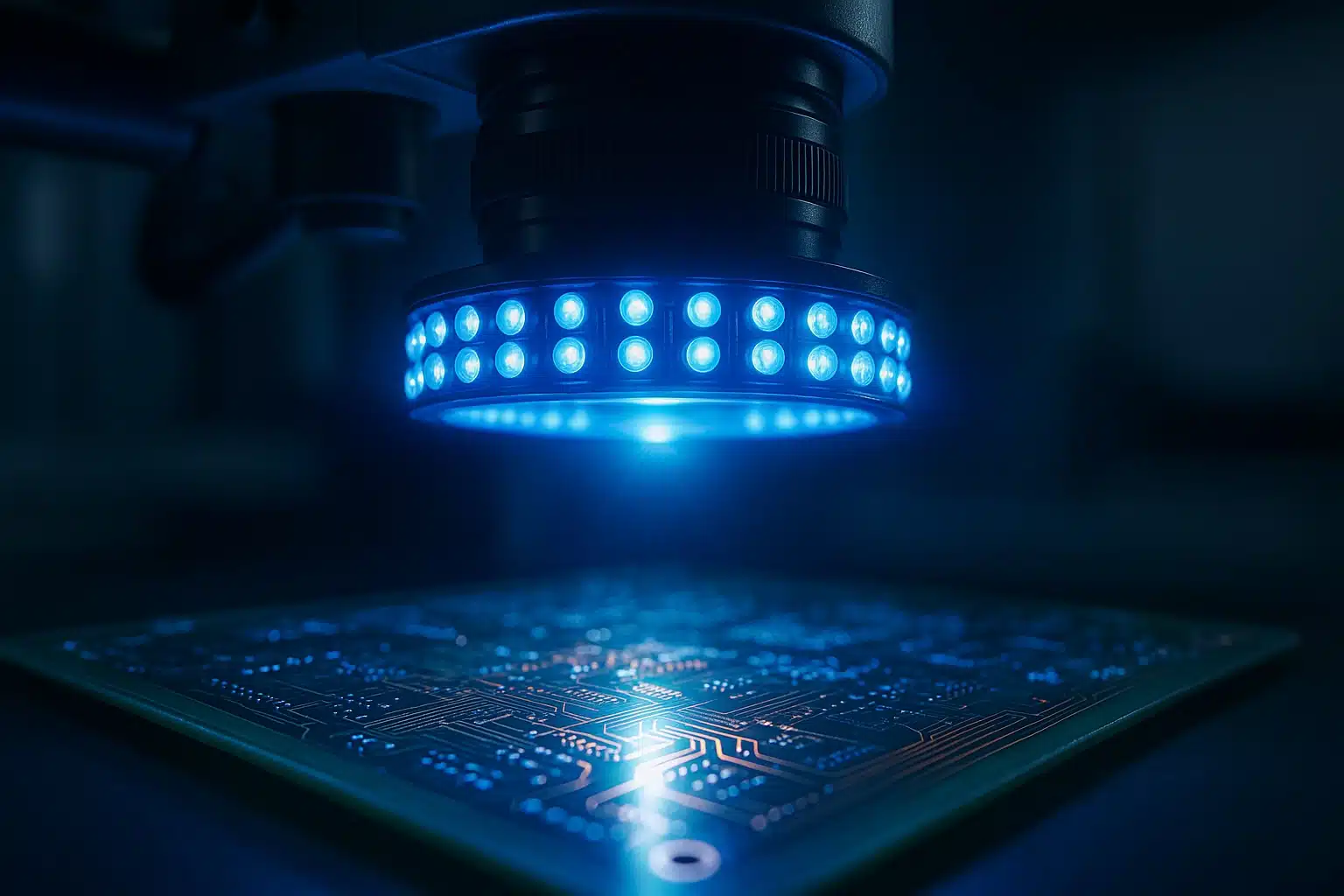
High-intensity 450 nm blue LED array illuminating a PCB during automated optical inspection, with copper traces glowing under the focused machine-vision lighting.
The practical uses of 450 nm blue LEDs in machine vision span a wide range of industries. In electronics manufacturing, blue LED ring lights or bar lights are common light sources used to inspect circuit boards (solder joints, component presence, etc.), especially when red or green lighting doesn’t provide enough contrast. For instance, certain conformal coatings or markings might fluoresce under blue illumination, revealing defects that are invisible under white light. In textile or food inspection, blue lighting can highlight surface textures or contaminants. Blue LEDs are also used in combination with filters: an indigo bandpass filter around 450 nm will block ambient light and pass only the LED’s output, which is great for a controlled imaging setup on a factory floor with overhead lamps.
One powerful technique is multi-spectral imaging. Here, a system might have several LED arrays of different colors (say UV, blue, red, IR) and take successive images under each. The blue LED image might show one set of features (like surface scratches, which scatter short wavelengths strongly), while an IR LED image might penetrate deeper, revealing sub-surface features or print beneath a plastic layer. By comparing these images or combining them, machine vision algorithms can make more robust decisions. Blue illumination, due to its shorter wavelength, tends to emphasize fine surface details (small scratches or dust) because of higher scattering. It also has the benefit of being visible to the human eye (unlike IR), so an operator can see the illumination and align things by eye if needed.
Another area where 450nm blue LEDs shine (literally) is in fluorescence-based inspection, particularly when paired with 365nm light sources. Some quality control processes apply fluorescent dyes or use materials that naturally fluoresce under 365nm and 450nm blue light. For example, certain lubricants or leak-detection markers glow under blue or UV light, so a blue LED can cause these to emit green or yellow light that cameras pick up. Blue is often preferred over UV because it’s less hazardous and many common fluorescence targets (like dyes, or even chlorophyll in plant imaging) have strong absorption around 450 nm. In machine vision, using a blue excitation source and a long-pass filter on the camera (to block the blue and pass the fluorescence) creates a system that sees only the glowing regions, making them stand out with high contrast.
Integration considerations: If precise control of intensity is needed (for example, to avoid saturating a camera or to adjust for different reflectivities), blue LED lights can be made dimmable through either current control or pulse-width modulation. It’s also common to include a photodiode or other detector for feedback. For instance, a calibrated photodiode could monitor the light output and help regulate it over time or compensate for temperature changes. Tech-LED also offers photodiodes which can be paired with LEDs for such feedback loops or for sensing the reflected light in inspection setups. Overall, 450 nm LEDs are a versatile tool in the machine vision toolbox – they can work solo or in tandem with other wavelengths to solve complex inspection challenges.
Blue LEDs in mixed-spectrum and plant-growing applications
Beyond traditional machine vision, 450 nm blue LEDs find uses in any application requiring high-energy visible light. In mixed-spectrum illumination systems (for example, simulators or specialized lighting rigs), blue LEDs provide the short-wavelength end of the spectrum. If you need full spectrum or tunable white light, an array of red, green, and blue LEDs can be combined – here the 450 nm LED contributes the “blue” component and can mix with others to create various colors or white when needed. In stage lighting or display lighting, for instance, intense blue LEDs are used to create vivid effects or to mix into different colors. High-power blue LED fixtures are common in stage lighting for theaters and concerts, where a deep blue wash or dynamic color mixing is desired. The efficiency of modern blue LEDs also means these light sources can achieve the required brightness with less heat and power draw than older technologies.
One particularly interesting domain is horticultural lighting for plant growing. It turns out that plants are sensitive to blue light (as well as red). Typically, growers use a combination of blue and red LEDs to optimize photosynthesis and control plant morphology. Blue light (around 450 nm) is absorbed by chlorophyll and also influences plant developmental processes – it keeps plants more compact and can enhance certain pigmentation or nutrient profiles. Studies in photobiology indicate that blue photons (400–500 nm) are about 20% less photosynthetically efficient than photons from the most common red LED (660 nm) in some species, yet they are crucial for regulating growth. Most “full spectrum” LED grow lights therefore include a fraction of blue light (often 5–30% of the photon output) alongside red. The blue ensures plants don’t grow too leggy (excess stem elongation is suppressed) and can improve leaf thickness and quality. So a 450 nm LED is a key part of horticulture LED solutions, balanced with red and sometimes green or far-red outputs to mimic sunlight’s effects.
Outside of plants, blue LEDs have even made their way into medical and biomedical uses. For example, blue LED light therapy is a known treatment for certain skin conditions (though those often use slightly shorter ~415 nm LEDs to target porphyrins in acne-causing bacteria). Similarly, blue illumination is used in some dental curing lights and for phototherapy on neonatal jaundice (commonly around 450–470 nm to break down bilirubin). These are specialized applications but they underscore the versatility of the 450 nm wavelength. In laboratories, companies like Thorlabs supply 450 nm LED sources with precise driver control for experiments ranging from microscopy to optical communications. Whether it’s to grow better seedlings or to calibrate a scientific instrument, the combination of high intensity and relatively low power consumption makes the 450 nm LED a compelling light source.
Electrical design: drivers, forward voltage/current, dimming
Integrating a 450 nm LED into an electrical circuit requires understanding its driving requirements. A single high-power blue LED typically has a forward voltage (Vf) around 3.0 to 3.3 volts at its nominal current. For example, at 350mA (a common test current for many LEDs), the forward voltage might be ~3.2 V for a royal blue LED. If you drive it at 700 mA, the voltage might rise slightly to ~3.4 V. This means you can’t simply connect it to a 5V or 12V supply without proper current limiting. The simplest method for low-power LEDs is a series resistor as a current limiter, but for high-power LEDs that draw hundreds of mA, a dedicated constant-current driver circuit is needed. These LED drivers regulate the current to a set value regardless of supply voltage fluctuations or LED forward voltage variation. They often use switching regulator topologies for efficiency (linear regulators would waste too much heat at these currents).
When designing the driver circuit, consider how many LEDs you need and whether to place them in series or parallel. Series connection is preferred for LEDs in general (the same current flows through all, ensuring equal brightness). For example, three 450 nm LEDs in series might have a total forward voltage of about 3 × 3.2 = 9.6 V, which can be driven from a 12V supply with an appropriate constant-current driver. If you put LEDs in parallel, each needs its own current regulation or ballast resistor to account for slight Vf differences. Many off-the-shelf LED drivers (including those originally designed as laser diode drivers) can serve for driving high-power LEDs, as they both require stable current. Just ensure the driver can handle the LED’s forward voltage and the LED power at your chosen current. Also, check if the LED driver has a dimming input – typically analog dimming (adjusting current) or PWM dimming (rapidly switching on/off) to achieve different brightness levels for 450nm blue LEDs.
In practice, 450 nm LEDs are highly dimmable and can be driven over a wide current range. For example, you might run a high-power LED at only 100 mA for a low output, or push it to 1000 mA for a brief high-intensity strobe, depending on the LED’s rated operating current limits. Rapid switching (for strobes or PWM) is possible since LEDs have nanosecond-scale intrinsic response times, but the driver circuit and parasitics will practically limit the switching speed to maybe microseconds – which is more than enough for typical imaging frame rates. One should also implement proper electrical protection: since LEDs are diodes, they are polarized – reverse voltage beyond a few volts can damage them, so avoid hooking them up incorrectly (observe the anode/cathode orientation). Additionally, it’s good practice to include a transient suppressor or at least a capacitor in the driver circuit to prevent voltage spikes when switching, which could overstress the LED.
Regarding the printed circuit board layout for LED drivers: keep the LED leads short and use sufficiently wide traces for the current. If using a switching driver, follow the recommended layout for the inductor, diode, and switch to minimize electromagnetic interference. The driver will dissipate some heat too, so plan for that in the enclosure. Finally, consider how you will connect the LED module – soldering wires directly vs. using connectors. High-power LED modules (like COBs) might have solder pads or even mounted lead wires; ensure any connector you use can handle the current without significant voltage drop. In summary, treat the 450 nm LED like any high-power diode load: drive it with a reliable constant current, mind the forward voltage, and provide flexibility for dimming. That will guarantee a stable light output for your inspection system across various conditions.
Reliability, RoHS, and system-level considerations
Blue LEDs, like most modern LEDs, are very robust if used within specs. Many are rated for tens of thousands of hours of operation (the L) when utilizing 450nm blue technology.70 metric – time to 70% of initial luminous output – can be 50,000 hours or more). To achieve this in practice, you should derate the LED (not always running at the absolute maximum current) and keep it cool. Running a 450 nm LED at a moderate current instead of pushing it to the limit can significantly improve its lifespan. Manufacturers bin LEDs by wavelength and brightness, so when building a system with multiple LEDs, ensure you procure from the same bin or at least account for slight variations. At 450 nm, a bin tolerance might be ±5 nm, which is usually not an issue for appearance but could matter if you have a tight detection band – in such cases, you might tighten the spec to a particular dominant wavelength bin for all your LEDs.
From a regulatory standpoint, 450 nm LEDs themselves are generally RoHS compliant (they do not contain heavy metals like mercury, and most modern LED packages avoid lead-based solder). Still, when incorporating them into a product, make sure all components (LEDs, optics, wiring, PCB materials) meet the environmental regulations applicable to your region, such as RoHS and REACH in the EU. If your inspection lighting is part of a machine that will be used in various markets, consider safety standards compliance – for example, IEC 62471 for photobiological safety to ensure that the blue light output doesn’t exceed safe limits for operators. Most LED datasheets will mention the risk group classification (RG0 = exempt, RG1, etc.) based on drive current and distance. At 450 nm, the threshold for risk groups in terms of radiance is stricter than for longer wavelengths (because the blue light hazard weighting is higher than for red/IR), so if you have an ultra-bright LED array focused in a small area, it could be classified as Risk Group 2 (moderate risk). The solution is usually to add diffusers, expand the beam, or enforce a minimum viewing distance to stay in RG1 or exempt.
At the system level, also consider how the blue LED lighting interacts with other parts of the machine. Blue LEDs emit very intense visible light – if there are other optical sensors nearby (not related to the vision system), could they be affected? It’s uncommon, but some ambient light sensors or other instrumentation might pick up scattered blue light. Using proper shielding or narrow-band filters can confine the illumination to the intended imaging area. If the system operates alongside humans, you might add simple indicators or interlocks for safety: for example, a warning LED or light when the high-power blue LEDs are on, just as a precaution (blue light can cause afterimages or visual discomfort if one accidentally looks directly at a bright source). Maintenance and calibration are another consideration, particularly for systems using 365nm and 450nm LEDs. LEDs don’t typically “burn out” suddenly; they gradually dim, especially in the case of 450nm blue LEDs. For a critical inspection system, you might need to periodically verify that the illumination level at the camera is within spec. This can be done by reading the camera exposure settings or by using a photometric sensor. Since blue LEDs are quite stable, you might only need to check annually or semi-annually. Swapping out an LED module is straightforward when needed – just ensure the replacement part is the same specification (or compatible) and recalibrate if necessary to ensure optimal performance of 450nm blue LEDs. Finally, keep in mind future upgrades: the LED industry continually improves efficacy. It might be worth designing the lighting module to be replaceable so that in a few years, you could upgrade to a new LED board that provides more output for the same input power. A bit of foresight can make your inspection electronics more future-proof.
Selection checklist: choosing the right 450nm LED for your application
With a solid understanding of 450 nm blue LEDs, let’s summarize key points to consider when selecting and implementing one:
- Wavelength & Spectrum: Confirm the LED’s dominant wavelength (≈450 nm) and spectral width. Ensure it matches any filters or sensor sensitivity requirements (e.g., a narrow spectrum might be needed for specific sensors or detector types).
- Optical Output of 365nm and 450nm blue LEDs can vary significantly based on their application. Determine the radiant flux or luminous flux needed. How many milliwatts or lumens does your application require? Keep in mind that blue light at 450 nm has low luminous efficacy for human vision, so focus on radiometric power for machine vision. Use multiple LEDs or higher drive currents if extremely high intensity is required.
- Package Type: Choose a package that suits your integration. Options range from single-die SMD LED packages (e.g., 3535 or 5050 SMD) to multi-die COB modules. For tight spaces, a compact SMD might be ideal; for maximum output, a COB or array could be better. Also plan for mounting and cooling (using proper heat sinks or metal-core PCB boards).
- Lens & Beam: Decide if you need a built-in lens or secondary optics. A narrow viewing angle LED can deliver higher intensity on target, but a wider beam might be needed for uniform coverage. You can always add optics later, but starting with the right beam profile simplifies design. Check the LED’s datasheet for lens options and beam shape.
- Electrical Drive: Ensure you have a suitable driver. Check the forward voltage (~3.2 V) and operating/forward current (350 mA, 700 mA, etc.), and choose a constant-current driver that meets those. Plan how to dim or pulse the LED if needed – some drivers offer PWM or analog dimming control for adjustable brightness. Don’t forget to include a proper driver circuit or use an LED power supply module that can provide stable current.
- Thermal Management: Verify the thermal requirements. If the LED will be run at high power continuously, incorporate a heat sink (and possibly a fan). Use the thermal resistance data to estimate junction temperature under your conditions. Remember, keeping the LED cool ensures long life and consistent light output.
- Reliability & Compliance: Look for lifetime data (e.g., L70 hours) in the LED’s datasheet. Choose components that are RoHS compliant and meet any necessary safety standards (like IEC 62471 for photobiological safety). If the light will be observed by operators, consider diffusers or shields to reduce glare. For production consistency, use LEDs from the same bin or lot, or plan for slight variations in output.
- Sensing & Feedback: If your application demands consistent brightness or calibration over time, consider using a photodiode or feedback system. This can correct for any output drift due to temperature or aging, especially in 450nm blue LEDs. For example, a reference detector can monitor the light level and adjust the drive current to keep illumination constant.
What is a 450 nm LED and how does it differ from other LED wavelengths?
A 450 nm LED emits blue light with a peak wavelength around 450 nanometers. Compared with other LED wavelengths, such as 365 nm (UV) or 520 nm (green), a 450 nm LED is in the visible blue spectrum and is commonly used for applications requiring high-energy visible light, precise color rendering in displays, or as a pump source for phosphors that produce white light. Its photon energy is higher than longer visible wavelengths but lower than ultraviolet and near-infrared (NIR) wavelengths.
What are common applications of 450 nm LEDs?
450 nm LEDs are used in a wide range of applications including backlighting for LCDs, stage and architectural lighting, blue laser pumping, fluorescence excitation in laboratory instruments, photobiomodulation research, and horticultural lighting when combined with other wavelengths. They are also used in optical sensors and machine vision where high-contrast blue illumination is required.
How efficient are 450 nm LEDs and what affects their efficiency?
Efficiency of 450 nm LEDs depends on chip design, materials (commonly gallium nitride-based), heat management, and drive current. External quantum efficiency and luminous efficacy typically peak at moderate drive currents and drop at higher currents due to thermal roll-off. Proper heat sinking and current regulation improve efficiency and lifespan.
Can 450 nm LEDs be used for photobiomodulation or medical therapy?
Research has explored blue light around 450 nm for certain photobiomodulation effects, including wound healing modulation and antimicrobial effects, but outcomes vary and safety must be considered. Many clinical photobiomodulation treatments use red or near-infrared (NIR) wavelengths instead because they penetrate tissue more deeply. For any medical use of 450 nm LEDs, follow evidence-based protocols and regulatory guidance.
What safety considerations are important when working with 450 nm LEDs?
450 nm blue light can cause visual discomfort and potential retinal hazard at high intensities or prolonged exposure. Use appropriate eye protection, avoid staring directly into the LED, and implement current limiting and thermal protection in designs. For devices interacting with skin or eyes, adhere to safety standards and exposure limits provided by organizations like IEC and local regulators.
How do you drive and control a 450 nm LED in an electronic circuit?
Drive a 450 nm LED with a constant current source matched to the LED’s forward current rating. Use appropriate series resistors or dedicated LED drivers for current regulation, and add PWM dimming if variable intensity is needed. Ensure proper thermal design so junction temperature remains within the specified range to maintain performance and longevity.
What factors determine the lifespan and reliability of a 450 nm LED?
Lifespan depends on operating current, junction temperature, thermal management, solder and package quality, and environmental factors such as humidity. Running the LED within its rated current and ensuring efficient heat sinking significantly extends lifetime. Degradation of phosphors or die can lead to color shift and lumen depreciation over time.
How does a 450 nm LED compare to NIR LEDs for sensing and communication?
450 nm LEDs and NIR LEDs operate in very different spectral regions, offering distinct advantages. A 450 nm LED provides high contrast for visible imaging and excites certain fluorophores effectively, whereas NIR LEDs penetrate materials better and are commonly used in night-vision, biometric sensors, and fiber-optic communication. Choice depends on the application’s optical properties, required penetration depth, and detector sensitivity.