520 nm green LEDs are crucial in industrial vision systems and agricultural sensors. In machine vision, this green wavelength aligns with peak camera sensitivity and helps produce balanced white-light illumination for accurate imaging. In agricultural applications, green light is strongly reflected by plant foliage, providing a means for canopy imaging and photosynthesis detection proxies like green-based vegetation indices. Careful illumination design at 520 nm improves measurement accuracy, signal-to-noise ratio (SNR), and overall system robustness. This article explains why technical teams should consider 520 nm LED light sources for machine vision lighting, greenhouse monitoring, and field-deployed sensor modules.
What Defines a 520 nm LED Wavelength?
A “520 nm LED” refers to an LED whose peak light emission is around 520 nanometers, squarely in the green portion of the visible spectrum. This wavelength is covered under visible LED products in the Visible LEDs (400–800 nm) category. Semiconductor material composition determines the LED’s wavelength: modern green LEDs at 520 nm typically use indium gallium nitride (InGaN) active layers, which can be tuned to emit across the entire visible range from violet (like a 405 nm LED) to green. By adjusting the indium content, manufacturers achieve a peak wavelength ~520 nm. Earlier-generation green LEDs made from gallium phosphide (GaP) emitted in the 560–570 nm range but with limited brightness; in contrast, InGaN-based green emitters (around 515–535 nm) offer much higher luminous intensity.
At 520 nm, the LED’s output appears as a pure green color to the human eye. The exact spectral profile is narrowband: for example, a typical 520 nm LED’s optical specifications list a peak wavelength of 520 nm with a dominant wavelength ~526 nm and a spectral half-width of ~30–36 nm. In other words, most of the light energy is emitted in a tight wavelength range (unlike a broadband lamp). For context, 520 nm sits between shorter blue-cyan wavelengths (e.g. a 450 nm LED) and longer red wavelengths (e.g. a 660 nm LED) in the visible spectrum. It is also well above the ultraviolet bands (covered by UV & Near-UV LEDs) such as 365 nm (near-UV as in a 365 nm LED) or deep UV-C (for example a UV-C LED), and below the near-infrared region that starts around 700 nm (leading into SWIR wavelengths). Defining a 520 nm LED is therefore both a matter of material science – using an InGaN diode structure – and specifying an optical peak in the green spectrum around that 520 nm point. (For a broader reference on LED wavelength categories, see our LED Wavelength Guide.)
How Do 520 nm LEDs Interact with Cameras and Sensors in Imaging?
Machine vision cameras and optical sensors often respond strongly to green wavelengths. The human eye’s peak sensitivity is around 555 nm (green), and similarly many image sensors (especially color CMOS/CCD sensors) have quantum efficiency that peaks near the green band. For example, one industrial camera sensor achieves its highest QE (~61%) at about 520 nm for the green channel. In a color camera’s Bayer filter array, green pixels are doubled in number (two green filters for every red and blue), underscoring the importance of green light in capturing detail and luminance. As a result, illuminating a scene with a 520 nm LED light source can yield a very strong signal on camera – the sensor’s green pixels receive abundant light, improving image brightness and potentially increasing the signal-to-noise ratio for features of interest.
In monochrome imaging systems (which have no color filters), 520 nm still lies in a highly sensitive region of a silicon sensor’s responsivity curve. That means a monochrome machine vision camera will efficiently detect light from a green LED, often more so than deeper red or violet light. Green illumination can also enhance contrast for certain targets. For instance, a red-colored object or marking will appear nearly black under green LED lighting (since red surfaces absorb green light), allowing vision algorithms to detect defects or text with higher contrast. Conversely, when balancing multi-color illumination for true-color imaging, a 520 nm emitter provides the green component in an RGB LED system (complementing blue and red LEDs) to simulate white light. In summary, 520 nm LEDs pair well with camera sensors by aligning with their peak sensitivity and offering a versatile visible-light illumination that human operators and machine algorithms can both leverage in inspection systems.
Why Choose 520 nm vs 450 nm or 660 nm in Agricultural Systems?
In agricultural sensing, the choice of LED wavelength impacts which aspects of plant physiology are being probed. Blue (~450 nm) and red (~660 nm) light correspond to chlorophyll’s absorption peaks – plants strongly absorb these for photosynthesis, hence those colors are common in grow lamps and in active photosynthesis detection sensors. That makes red and blue LEDs effective for stimulating growth and for certain indices like the classic NDVI (Normalized Difference Vegetation Index) which uses a red band and a near-infrared band (e.g., IR/NIR LEDs) to gauge plant vigor. (Some advanced indices even incorporate short-wave infrared, using specialized SWIR LEDs for water content sensing, though those lie beyond the visible spectrum.) However, those wavelengths can become “too effective” at high leaf densities – a healthy leaf absorbs nearly all red light, causing NDVI to saturate. Green light at 520 nm, by contrast, is less absorbed by chlorophyll and more reflected. While this means green LEDs are less useful for driving photosynthesis, it makes them very useful for sensing and imaging plant health. A green-based index (GNDVI) replaces the red band with green and is more sensitive to chlorophyll variations in dense crops. Because leaves still reflect a substantial amount of green, the GNDVI can detect changes in chlorophyll content even when NDVI is maxed out, and it has a higher saturation point for monitoring well-fertilized, deep-green canopies.
Another reason to choose 520 nm in active crop monitoring is penetration and canopy structure. Green photons penetrate deeper into leaf tissue and plant canopies compared to red or blue photons, which tend to be absorbed in the upper layers. This means a 520 nm LED illuminator can glean reflectance information from deeper leaf layers or lower canopy leaves that red/blue light might never reach. In practical terms, a sensor using a green LED may capture more uniform signals across a thick crop canopy, whereas a red-based measurement might only read the topmost leaves. Additionally, certain plant pigments (like some anthocyanins or stress indicators) have distinct responses in the green spectrum. In fact, one portable crop sensor design switched its measurement LED from 655 nm red to 520 nm green specifically to target absorption by free anthocyanin compounds. In summary, 520 nm occupies a middle ground: it’s not as photosynthetically active as blue or red for plant growth, but that very property – being moderately reflected rather than fully absorbed – makes green LED light ideal for detecting subtle changes in leaf physiology and canopy condition that other wavelengths might miss.
Green LED Fundamentals for Photosynthesis Detection and Canopy Monitoring
The reason plants look green is fundamental to using 520 nm LEDs in crop sensing. Chlorophyll pigments absorb strongly in the blue (~430 nm) and red (~660 nm) parts of the spectrum, but much less in the green range. As a result, healthy leaves have very low reflectance in blue and red (most of that light is absorbed) yet significantly higher reflectance in the green. The spongy mesophyll inside leaves also scatters green light, so that some passes through or bounces back out of the leaf. In practical terms, shining a green LED on foliage yields a measurable reflectance return – more so than with a red or blue LED – making green illumination useful for nondestructive monitoring of plant health. One study noted that reflectance in chlorophyll’s primary absorption bands (blue and red) changes little with different chlorophyll levels (because even a small amount of pigment absorbs them almost fully), whereas reflectance in the green band remains higher and can vary as chlorophyll content changes. This means a decline in chlorophyll (e.g. from nutrient stress or senescence) will often show up as an increase in green reflectance (leaves look more yellow-green), a useful signal for detectors.
Using 520 nm LEDs for photosynthesis-related detection thus leverages the balance between absorption and reflection. A green LED will not drive photosynthesis as efficiently as a red or blue lamp (since much of the green light is not absorbed by leaves), but that “wasted” light is exactly what sensors catch as reflectance. For canopy monitoring, a green LED light source can illuminate plant leaves without saturating the top layer, and the returned green light carries information about leaf biochemistry and structure from the surface and slightly deeper layers. Engineers designing crop sensors often pair a known-intensity green LED with a calibrated photodiode detector to measure the fraction of light reflected by the crop. The reflectance percentage at 520 nm serves as a proxy for chlorophyll concentration and overall plant “greenness.” For example, a high reflectance at 520 nm may indicate lower chlorophyll content (since less green is being absorbed), whereas a lower reflectance (darker leaves under green illumination) suggests pigment-rich, photosynthetically active foliage. By understanding these fundamentals – that green light penetration and moderate absorption reveal subtle differences – one can design detection systems that use 520 nm LEDs to track crop health in real time.
Optical Specifications of 520 nm LEDs: Wavelength, Intensity, and Beam Control
When evaluating a 520 nm LED, key optical specifications include its exact wavelength, output intensity, and emission beam pattern. The peak wavelength is typically specified as 520 nm ± a few nanometers, with a dominant wavelength in the mid-green region (e.g. 525–530 nm). Manufacturers also note the spectral bandwidth (around 30 nm FWHM as mentioned above) and how consistent the wavelength is across temperature or drive current. LED intensity is often given in millicandelas (mcd) or as radiant flux (milliwatts) at a standard drive current. For instance, an indicator-type 520 nm LED might emit a few thousand mcd, whereas high-power “super bright” green LEDs can output many lumens of green light. Intensity and brightness depend on the LED chip size, efficiency, and drive current – a larger die or multiple-die module driven at higher current yields more optical output power (with the trade-off of more heat). It’s also important to consider how brightness is perceived: at 520 nm the human eye’s luminous efficiency is relatively high, so a modest radiant flux can appear very bright (advantageous for visible signaling or illumination).
The emission pattern of a green LED is another critical specification. Standard epoxy-encapsulated or SMD LEDs without special optics typically have a Lambertian radiation profile – roughly a 120° full-angle where intensity falls to half at around 60° off-center. This wide dispersion is useful for general illumination but can be inefficient if you need to project light onto a small target or over a distance. To address this, many 520 nm LEDs come in packages with built-in lenses (narrow viewing angles of 20–30°) or are paired with secondary optics to collimate the beam. In practice, achieving good collimation with LED sources requires carefully designed optics, since narrowing the beam too much can reduce the usable intensity on target. Similarly, reflectors or optical lenses can shape the beam into a line or other pattern for machine vision applications requiring uniformity. In lab setups, engineers sometimes even couple the LED light into an optical fiber for remote delivery – though efficient coupling requires matching the LED’s emitting area and numerical aperture with the fiber. Ultimately, beam control is about balancing coverage versus intensity: a bare 520 nm LED gives broad coverage, whereas a collimated or lens-focused LED concentrates brightness on a smaller area (useful for imaging specific fields of view or distant targets).
High-Power 520 nm LED Packages: SMD, 5050 SMD, and Surface-Mount Modules
Green LEDs at 520 nm are available in a variety of package types, from tiny indicator lamps to large high-power modules. The type of LED package chosen influences performance in terms of output and thermal management. At the low-power end, traditional through-hole LEDs (like 3 mm and 5 mm “bullet” lamps) can emit 520 nm light. These have two wire leads (an anode and cathode pin) and a round epoxy lens. A 5 mm LED bulb of this type is suitable for status indicators or small-area illumination, but its power is limited by the small LED chip and simple packaging. For machine vision or horticulture, engineers typically need brighter, more robust packaging. Surface-mount (SMD) LEDs became the standard for higher-power visible LEDs because they can be mounted directly onto circuit boards for better heat dissipation. For instance, a green LED in a 5050 SMD package (a 5.0 × 5.0 mm plastic leaded package) can accommodate a larger die or even multiple dies. (Many RGB LED modules use a 5050 SMD footprint, combining separate red, green, and blue chips in one package for color mixing.) A single-color 520 nm high-flux LED in a 5050 SMD can deliver significantly more light than a 5 mm through-hole lamp, thanks to a bigger emitter area and higher drive current capability.
Beyond standard SMD packages, there are custom high-power modules and chip-on-board solutions for 520 nm LEDs. In chip-on-board (COB) assemblies, multiple green LED chips are bonded directly onto a substrate and encapsulated, effectively creating one large LED die on a board. This allows extremely high light output and easier heat sinking, since the COB module can be mounted onto a metal core PCB or heat sink directly. Other high-power formats include specialized surface-mount packages with integrated thermal pads – for example, Tech-LED’s SMBB high-power LED package or the ceramic EDC series. These packages are designed to handle higher currents (often one watt or more of dissipation) and to be screwed or reflow-soldered onto heatsinked boards, making them easy to mount in designs. When using high-power 520 nm LEDs, the mounting and cooling become crucial: one must ensure good thermal contact to a heat sink and consider the PCB layout (thermal vias, etc.) to draw heat away from the LED. In return, these advanced packages provide very bright green light output and reliability for industrial use, far beyond what a simple indicator LED could achieve.
Designing 520 nm LED Light Sources for Machine Vision & Imaging
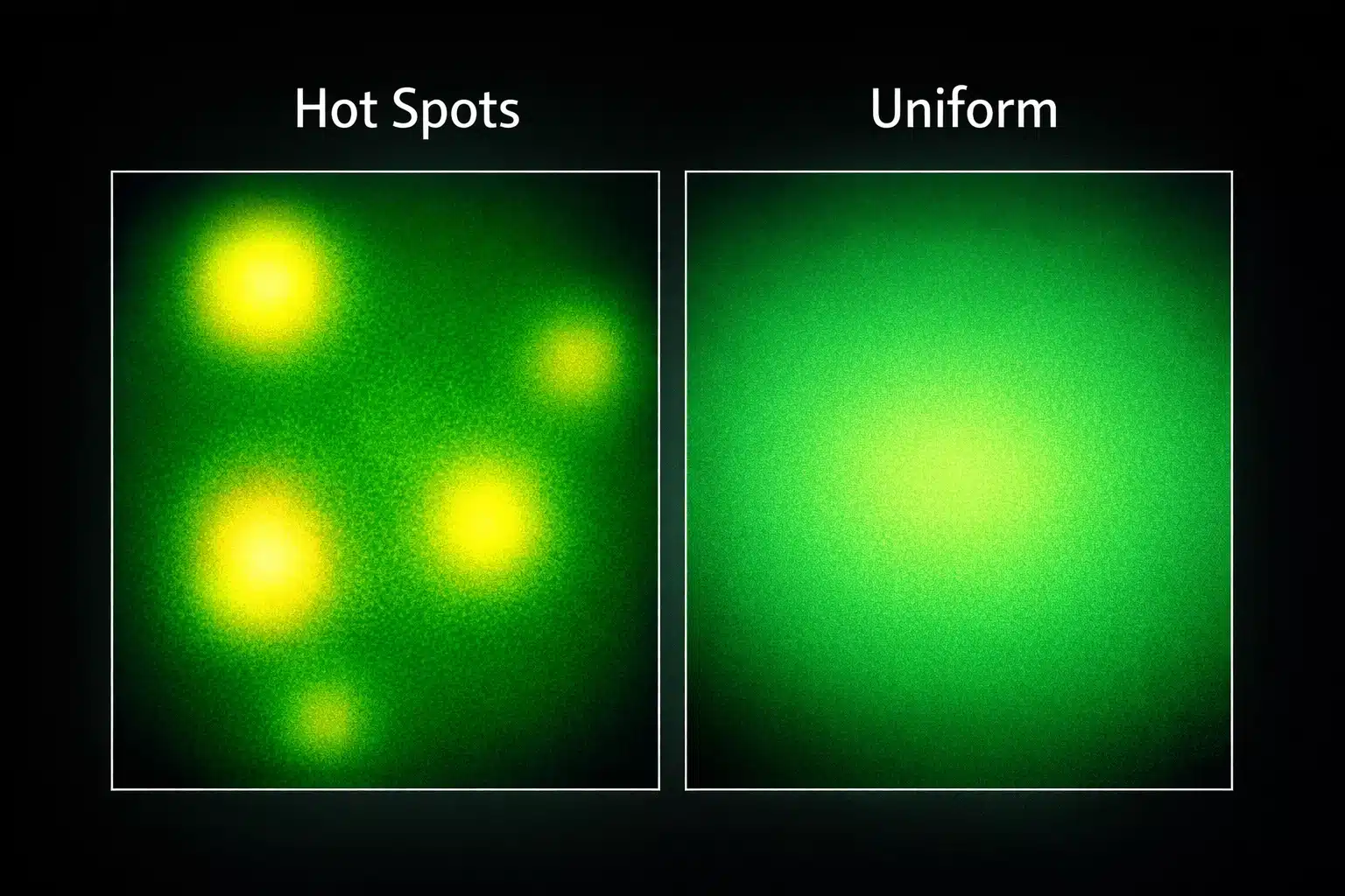
When implementing a 520 nm LED in a vision system, the optical design must ensure that the target is illuminated evenly and with sufficient intensity. In industrial inspection, non-uniform or inadequate lighting can lead to missed defects or noisy images. Thus, engineers often use multiple green LED emitters or high-power LED modules arranged to cover the field of view uniformly. For example, a line-scan camera inspecting moving plant material might use a linear array of 520 nm LEDs (with a cylindrical lens) to create a uniform line of green light across the conveyor. An area-scan imaging setup, on the other hand, may employ a ring light or diffused panel of green LEDs to minimize shadows and hot spots on reflective surfaces. According to machine vision lighting guidelines, uniform illumination without glare or shadows is crucial for reliable image analysis. Achieving this often involves diffusers (to scatter the LED output) and careful positioning of the light source relative to the camera and object.
520 nm LED light sources can be tailored to the specific imaging task. If fine color discrimination is needed (say, sorting produce by subtle color differences or detecting blemishes on green foliage), a broad, high-CRI white light might be unnecessary – a pure green illumination can enhance contrast for features that reflect green differently. Conversely, in an RGB imaging system, the 520 nm LED might be one component of a multi-color illuminator, combined with blue and red LEDs and controlled to achieve a desired color balance. Many machine vision systems also synchronize lighting with the camera’s exposure. A dedicated LED controller can strobe the 520 nm LEDs in sync with the camera shutter, freezing motion and allowing higher drive currents momentarily for extra brightness. This strobing technique increases effective illumination without overheating the LEDs, since the duty cycle is low. Thermal design remains important even in pulsed operation – heat sinks and proper ventilation ensure the green LEDs stay within temperature limits for stable output. In summary, designing a 520 nm LED light source for imaging involves selecting the right optics (e.g. diffuse vs. collimated), ensuring uniform coverage, and driving the LEDs with a suitable power supply or pulse controller to meet the camera’s needs for brightness and timing.
Designing 520 nm LED Light Sources for Greenhouses and Agricultural Sensors
Greenhouse lighting and field-deployed sensor units impose different design constraints, but 520 nm LEDs can play a vital role in both. In greenhouses, the primary lighting for plant growth is usually a mix of red and blue (to maximize photosynthesis), but adding green LED light has some advantages. Green wavelengths penetrate deeper into plant canopies, so supplementing a primarily red/blue grow light with 520 nm green can deliver light to lower leaves that would otherwise be shaded. It also produces a more visually balanced “white” illumination, which is beneficial for human workers in the facility (pure red/blue lighting can be uncomfortable to work under). From a design perspective, integrating green LEDs into greenhouse luminaires means ensuring their output is efficiently combined with other colors – often using diffuser panels or reflectors to blend the spectra. High-power 520 nm COB modules can be used in overhead lamps, provided there is adequate cooling. The power supplies for these LED fixtures must provide constant current and be rated for the humid greenhouse environment (encapsulated or conformal-coated drivers to prevent corrosion). Green LEDs generally run at similar forward voltages as blue LEDs (~3 V), so they can be wired in series strings on the same driver channels as the blues if needed, or separately controlled to adjust the light recipe.
For outdoor and field sensor systems – such as crop monitoring rigs on tractors or UAV (drone) based multi-spectral cameras – using a 520 nm LED requires focusing on ruggedness and measurement consistency. Active optical crop sensors sometimes include an onboard green LED emitter and a photodiode to measure reflectance, allowing them to operate day or night without relying on sunlight. A drone-mounted sensing module, for example, might flash a 520 nm LED and capture the reflected green light to compute a vegetation index on the fly. Because weight and power are limited on UAVs, efficient, high-intensity LEDs (and maybe optics to narrow the beam) are preferred so that the light can reach the canopy from altitude. Field units must also be built to withstand wide temperature ranges, dust, and moisture. This often means using sealed LED modules with an IP65+ rating and possibly adding protective coatings on the LED lens against UV exposure and dirt. Despite these challenges, the value is clear: using a controlled 520 nm illumination in such sensors yields more consistent data. In one study, a UAV-mounted spectral system employed a dedicated green band (~520–600 nm) along with red and NIR channels to distinguish between crop cultivars, significantly improving the ability to detect varietal differences in the canopy reflectance patterns. Whether in a greenhouse array or a field sensor, 520 nm LEDs must be integrated with attention to optics, power, and environmental protection – but when done right, they provide a crucial window into plant health that complements the red, blue, and infrared portions of the spectrum.
Electrical and Thermal Design: Forward Voltage, Power Supply, and Current Control
Driving a 520 nm LED properly requires attention to its electrical characteristics. Green InGaN LEDs have a forward voltage (VF) around 2.8–3.2 V at 20 mA (and higher at larger currents). This means a single LED can be powered from a low-voltage source (e.g. a 5 V supply) with appropriate current-limiting, but you cannot simply connect it to a 3 V battery without a driver. In circuits, multiple 520 nm LED dice are often placed in series – for example, a high-power module with 3 green LEDs in series will drop ~9–10 V, and larger COB arrays can have forward voltages of tens of volts, essentially a high-voltage source that requires proper isolation and safety design. As the forward voltage adds up, designers may need boost converters or higher-voltage drivers to drive these strings. Any LED light source should be driven by a constant-current power supply or driver to regulate the current. Unlike incandescent lamps, LEDs are current-driven devices: small changes in voltage can lead to large changes in current once the diode is in forward conduction. Thus, using a dedicated LED driver or current controller is crucial for stability. Simple resistor limiters might suffice for low-power indicator LEDs, but for high-power 520 nm LEDs a switching regulator or linear LED driver is preferred to maintain consistent brightness and avoid thermal runaway.
Thermal management goes hand-in-hand with electrical design. Green LEDs are reasonably efficient, but a significant portion of input power still turns into heat. Running a 520 nm LED at high drive current will raise its junction temperature, which can shift the wavelength (a few nm) and reduce light output. More critically, excessive heat accelerates LED degradation over time, lowering brightness and potentially altering the color. To mitigate this, design the PCB and mounting for optimal heat dissipation: use metal-core PCBs or attach the LED package to a heatsink with thermal interface material. Ensure air circulation or other cooling if the LEDs are in an enclosed space. It’s also good practice to operate high-power LEDs at a margin below their absolute maximum ratings. By giving the 520 nm diode some headroom (for instance, driving at 80% of rated current), you reduce stress and prolong its lifespan, especially in hot environments. Finally, include protection and control circuits: transient suppressors for ESD, and dimming or feedback control if you need to adjust intensity. A well-designed current control and thermal system will keep the green LED light source stable and reliable throughout its service life.
Measurement, Calibration, and Detection: Using Green LEDs with Photodiodes and Sensors
Integrating a 520 nm LED into a measurement or detection system requires careful calibration to ensure accurate readings. In a typical setup, the LED emits the light toward the target (e.g. plant leaves or a reflective surface) and a sensor (camera or photodiode) detects the returned light. To quantify something like “greenness” or reflectance, the system must account for the LED’s output intensity, the geometry of illumination, and the sensor’s sensitivity. One common approach is to include a reference channel or baseline measurement. For instance, an agricultural reflectance sensor might take a reading of the ambient light or use a calibrated white reference panel under the 520 nm illumination to normalize the readings. By comparing the light reflected off crops to the light from a known reference, the device can calculate reflectance percentage independent of factors like LED brightness drift or distance to target. Some designs even use a second photodiode aimed directly at the LED to monitor its real-time output as a reference, while another photodiode measures the light reflected from the plants – the ratio of the two gives a calibrated reflectance index.
When calibrating green LED-based instruments, it’s important to use proper radiometric units. Photodiodes and cameras respond to the radiant energy at 520 nm, so calibration should be done in terms of W/m² or photon flux, rather than just relying on human-visible brightness. Standard procedures might involve measuring the LED’s output with a calibrated lux meter or spectroradiometer at the operational current to know exactly how much light (in lumens or in watts of optical power) is being emitted. The sensor side can be calibrated by checking its response with known light levels or test targets of known reflectivity at 520 nm. In machine vision quality control systems, a green LED lighting setup may be calibrated by imaging a uniform green reference object and adjusting exposure until the sensor readings match expected values. Periodic calibration is advisable because LED output can change slightly over time and sensors can drift. Fortunately, green LEDs tend to have stable output over tens of thousands of hours, but factors like temperature or cumulative operating hours can introduce minor changes. By designing the measurement system with feedback loops (e.g., reference photodiode monitoring) and performing occasional checks with calibration standards, engineers can ensure that a 520 nm LED-based detection system delivers consistent and accurate results in the field.
Reliability and Long-Term Stability in Agricultural Environments
Green LEDs are generally very reliable light sources, but deploying them in agricultural environments calls for some extra considerations to maintain performance over the long term. One major factor is environmental sealing. Greenhouse and outdoor deployments expose LED modules to high humidity, water (irrigation splash or rain), dust, and agricultural chemicals. Any 520 nm LED assembly intended for these settings should have a suitable ingress protection rating (e.g., IP65 or higher), or be potted in a protective resin. This prevents moisture from corroding the LED leads or circuit board, and keeps dust or dirt off the LED lens. Dust accumulation on an LED can lower its brightness output or alter its beam pattern; in a field device, designers might include a transparent cover over the LEDs that can be periodically cleaned or self-cleaning coatings to shed dirt.
Thermal and mechanical stresses also affect long-term reliability. Agricultural systems often see wide temperature fluctuations between day and night, and seasonally. The expansion and contraction can stress solder joints or LED die bonds if the design does not account for it. Using LEDs in packages with good thermal matching to the PCB (for instance, ceramic-based packages or flexible interconnects) can improve durability. Vibration can be an issue on tractor-mounted units or drones – ensuring the LED and its wiring are secured to avoid fatigue is important. Over time, LEDs do dim gradually – a process known as lumen depreciation. A quality 520 nm LED run at its rated conditions might lose, say, 20% of its initial brightness after 50,000 hours of operation. However, if it’s overheated or over-driven, that degradation can accelerate. In harsh environments, chemical exposure (like sulfur compounds in farms) can sometimes tarnish LED encapsulants or leadframe materials, so choosing LEDs with resistant materials (gold wire bonds, silicone encapsulants instead of older epoxy formulations) improves longevity. It’s advisable to review manufacturer data (such as LM-80 test results for lumen maintenance) for the chosen LED if available. By designing for ruggedness – waterproof housings, proper heat sinking, and derating the drive current – a 520 nm LED illumination system can deliver stable performance over many years in the field. In fact, solid-state LEDs, when properly protected, far outlast traditional lamp solutions, reducing maintenance in agricultural facilities.
Selection Checklist for 520 nm LEDs in Vision and Agricultural Systems
- Wavelength & spectrum: Verify the LED’s peak wavelength (~520 nm) and spectral bandwidth align with your application’s requirements (chlorophyll sensitivity, camera response, etc.).
- Optical output: Ensure the LED’s brightness (lumens or mcd) is sufficient. For machine vision, use high-intensity or multiple LEDs if needed; for sensing, consider if a “super bright” output is necessary for signal quality.
- Package type: Select the appropriate LED package (through-hole vs. SMD vs. COB). High-power applications benefit from surface-mount packages or COB modules that can be mounted to heat sinks.
- Driver and power: Use a constant-current driver. Account for the ~3 V forward voltage of each 520 nm LED when designing power supply and series strings. Include current control to prevent overdrive.
- Thermal management: Integrate adequate heat sinking or thermal pads, especially for high-power 520 nm LEDs. Maintain junction temperatures within spec to avoid output drop and color shift.
- Optics & beam shaping: Plan the illumination geometry. Use diffusers for uniform coverage or lenses for focusing, depending on whether you need wide-area lighting or a collimated beam.
- Calibration & feedback: If used in a sensor system, calibrate the LED output and sensor. Incorporate reference measurements (e.g., a photodiode or white target) to ensure consistent readings and compensate for any LED aging or ambient light.
- Environmental durability: Choose LEDs with proper encapsulation (e.g., silicone lenses) and use sealed enclosures for outdoor/greenhouse use. Design for water-resistance, and consider easy cleaning or protective coatings to handle dust and debris on the LED optics.
- Multi-wavelength integration: For comprehensive spectral systems, combine the 520 nm green LED with other wavelengths as needed – for example, adding a blue 450 nm LED or red 660 nm LED channel for a fuller picture of plant conditions.
What is a 520nm LED and what does the 520 nm wavelength mean?
A 520nm LED emits green light with a peak wavelength around 520 nm, meaning its spectral output is centered near 520 nm wavelength. This designation helps specify color precisely for lighting, display, sensing, or horticultural applications. Devices described as 520nm or 520 nm wavelength are manufactured in various packages such as 3mm, 5mm, SMD LED (surface mount) and can be low-power indicator types or high power LED modules.
How does the peak wavelength affect performance of a 520nm led?
The peak wavelength determines perceived color and interaction with materials or sensors; a true 520nm peak wavelength provides a distinct green that matters for color matching, photosynthesis studies, and optical systems. Slight shifts from specified 520nm can occur with temperature, drive current, or high power operation; collimating lenses or lens optics are often used to manage beam quality and preserve the effective peak output on target.
Can I get a 520nm LED in high power or surface mount configurations?
Yes, 520nm LEDs are available as high power LEDs and as surface mount (SMD LED) packages. High power 520nm LEDs deliver greater luminous flux and often require thermal management, while SMD LED variants are compact for PCB assembly. Both types may be paired with collimating lenses or optics to shape a 120 degree or narrower beam depending on the application.
What lens options are used with 520nm LEDs to control beam angle?
Collimating lenses, secondary optics, and molded lens caps are commonly used with 520nm LEDs to control beam angle and intensity distribution. Typical beam patterns range from wide (~120 degree) down to narrow collimated beams; choosing a lens depends on whether you need flood illumination with a 120 degree spread or a focused spot using collimating lenses in high power systems.
Are there 520nm LEDs in 3mm and 5mm packages, and how do they differ?
Both 3mm and 5mm through-hole LEDs are offered at 520nm for simple prototyping and indicator uses. 3mm LEDs are smaller and draw less current, while 5mm LEDs are slightly brighter and easier to handle. For higher brightness or more compact PCB designs, designers often opt for SMD LED or high power LEDs with integrated lenses or external optics.
How do you drive a high power 520nm LED and is high voltage required?
High power 520nm LEDs typically require controlled constant-current drivers rather than high voltage. The current rating and thermal limits determine the driver selection; some arrays or modules may operate at higher voltage depending on series string configuration, but individual high power LEDs are driven by regulated current and need proper heat sinking to maintain peak wavelength stability and lifetime.
Can 520nm LEDs be combined with IR or other wavelengths in the same system?
Yes, 520nm LEDs can be combined with IR or other visible wavelengths in multi-spectral systems for sensing, imaging, or theatrical lighting. When combining with IR, consider optical filters and lenses to separate bands; collimating lenses and careful driver control help maintain consistent output from each source so the 520nm LED’s peak wavelength remains stable relative to the other emitters.
What considerations are important when choosing a 520nm led for optical projects?
Key considerations include desired peak wavelength accuracy (520nm), package type (3mm, 5mm, SMD LED, high power), beam angle (e.g., 120 degree or collimated), thermal management, and whether collimating lenses or surface mount placement are needed. Also evaluate driver requirements, possible high voltage series configurations, and whether additional optics or filters are required to achieve the target application performance.