630 nm red LEDs have emerged as critical components in modern biometric sensors, offering a precise light source for measuring physiological signals beneath the skin. This particular wavelength is ideal for penetrating human tissue to illuminate blood vessels while still being selectively absorbed by key biomolecules like hemoglobin. The result is a balanced interplay of absorption and reflectance: enough red light reaches subcutaneous capillaries and returns to a photodetector, carrying information about blood oxygen levels and pulse. For engineers designing optical sensors, the 630 nm LED provides a reliable, well-characterized illumination that can enhance the accuracy of heart-rate monitors, pulse oximeters, and even facial-recognition systems.
While 630 nm LEDs are famously used in other domains (for example, red grow-light bulbs for plant growth In horticulture, this discussion centers on their technical role in biometric and medical applications to help plants grow more effectively. applications. The performance requirements in these professional systems — precision light output, stable wavelength, and safety — differ significantly from consumer lighting uses. Below, we delve into what defines a 630 nm LED, how red light penetrates skin, and key considerations for integrating these LEDs into high-performance optical sensors and devices.
What defines a 630 nm LED wavelength?
A “630 nm LED” refers to an LED whose peak emission wavelength is approximately 630 nanometers, in the visible red portion of the spectrum. This wavelength is defined by the LED’s semiconductor material and bandgap energy — typically aluminum gallium indium phosphide (AlGaInP) for red LEDs. The LED chip is engineered so that when forward biased, it emits photons of around 630 nm (give or take a few nanometers). In practice, LED datasheets specify a dominant or peak wavelength (e.g., 625–635 nm bin) which identifies the LED’s color. This distinguishes a 630 nm device from, say, a 520 nm green or a 850 nm infrared emitter. Notably, 630 nm falls within the broad category of visible LEDs (400–800 nm), meaning the output is visibly red to the human eye.
The 630 nm specification is not only about color but also about how the LED’s output aligns with sensor needs. In biometric systems, a narrow emission spectrum is often desirable for filtering and analysis. Standard 630 nm LEDs typically have a full-width-half-max spectral bandwidth of around 20–30 nm. This monochromatic output provides consistency for optical measurements. Manufacturers achieve this wavelength precision, including the 630nm range, through material composition and epitaxy control during LED fabrication. In contrast to broad-spectrum “white” LEDs (which use phosphors), a 630 nm LED’s output is a direct emission line, making it easier to predict how it will interact with optical components and tissue. (For a broader overview of how LED wavelength choices impact applications, see our [[TODO_URL_WAVELENGTH_PILLAR:/blog/led-wavelength-guide/]].)
How red LEDs penetrate tissue for biometric sensing
When a 630 nm red LED shines on tissue, the light propagation is governed by absorption and scattering in skin and blood. Red wavelengths benefit from the so-called “optical window” in biological tissue: as the wavelength increases beyond the blue/green range, the effective penetration depth increases dramatically as described in tissue-penetration studies of the 600–1350 nm range. In fact, red and near-infrared light (600–900 nm) can reach millimeter-level depths in perfused skin, whereas shorter wavelengths are absorbed within a few hundred microns. Empirically, the 630 nm band can penetrate roughly 1–3 mm into tissue before being attenuated to 37% of its surface intensity as summarized in the same MDPI review. This depth is enough to reach the dermal microvasculature (where arterial pulses can be detected) but not so deep that all light passes through without interacting. The balance means a red LED can illuminate pulsating blood vessels and still allow some back-scattered light to escape the tissue and be captured by a sensor.
This penetration capability underpins common biometric sensor designs. In transmissive pulse oximetry, a red LED is placed on one side of a medium like a fingertip and a photodiode on the opposite side. The 630 nm light passes through the finger, modulated by the pulsatile blood flow, and the detector measures the varying intensity. Because red light can traverse a finger’s width (typically a few millimeters) with manageable attenuation, it’s effective for this configuration. In reflective photoplethysmography (PPG) used in wearables, the LED and photodiode sit side by side on the skin’s surface. Here the red light penetrates into the tissue and a portion is scattered back to the photodiode. Thanks to the ~mm-range penetration, even a reflective setup on the wrist or forearm can pick up arterial pulse signals. (Transmission mode is generally limited to thinner sites like fingertips or earlobes, whereas reflection mode can be used on wider body parts as described in MDPI’s discussion of PPG geometries.) In both cases, the red LED’s ability to reach the bloodstream and return with an optical signal is what enables heart-rate and oxygenation monitoring using light.
Optical properties of skin at 630 nm
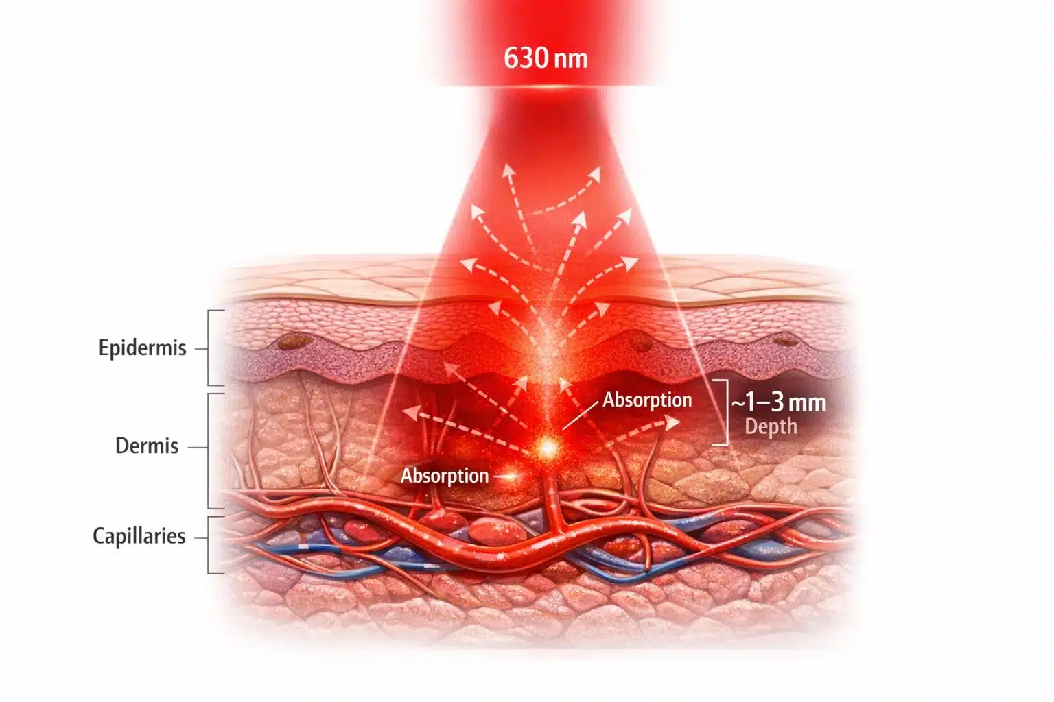
Figure 1. 630 nm Red Light Penetration in Skin
Cross-section showing how 630 nm red LED light scatters through the epidermis and dermis and is absorbed in the capillary bed, with an effective penetration depth of approximately 1–3 mm for biometric sensing.
The interaction of a 630 nm LED with skin is determined by skin’s optical properties at red wavelengths. Skin is a multi-layer medium: the outer epidermis (with melanin pigment) and the underlying dermis (with blood perfusion) are the primary optical players. At 630 nm, hemoglobin in blood is the dominant absorber of light, more so than water or other tissue constituents according to a Frontiers in Photonics discussion of tissue optical properties. Oxyhemoglobin and deoxyhemoglobin have specific absorption spectra that still exhibit significant absorption in the red range, though less than in the green. Melanin, the skin’s pigment, has a monotonically decreasing absorption towards longer wavelengths; by red and IR, melanin absorption is much lower than in the blue, especially around the 630nm range. This means that at 630 nm, although melanin does absorb some light (darker-skinned individuals will experience slightly more attenuation), the difference between skin tones is far less pronounced than at 450–500 nm. In essence, red light “sees” more of the blood and less of the melanin, improving measurement consistency across diverse populations (important for equitable biometric device performance).
Scattering is the other key optical property. Skin and blood are highly scattering for visible light due to the heterogeneity of cells and fibers. However, scattering in tissue is also wavelength-dependent — longer wavelengths scatter less. Red light at 630 nm undergoes less scattering than green light, and the scattering that does occur tends to be in the forward direction (high anisotropy) as characterized in Frontiers’ wavelength-dependent scattering discussion. Forward-directed scattering means photons can maintain their general trajectory deeper into tissue rather than bouncing directly back out, aiding penetration. In practical terms, a 630 nm LED’s output will diffuse through tissue in an expanding cone, illuminating a volume under the skin. The light will be partially absorbed by hemoglobin in capillaries and partially scattered multiple times. Eventually, some of those photons re-emerge from the skin (in reflective mode) or reach the far side (in transmissive mode) carrying the imprint of the pulsatile absorption changes. These optical characteristics — moderately low absorption by skin itself, strong but not saturating absorption by blood, and forward-biased scattering — explain why 630 nm is a “sweet spot” for biometrics. The red light produces a good signal contrast from blood flow while still propagating through the tissue layers of interest.
Comparing 630 nm to 520 nm and 850 nm illumination in sensors
How does a 630 nm red LED stack up against other commonly used biometric illumination wavelengths, like 520 nm green or 850 nm near-infrared? Each wavelength has trade-offs in penetration depth, signal strength, and application suitability. Green (~520 nm) light is strongly absorbed by hemoglobin — even more strongly than red is. This makes green LEDs excellent for capturing blood pulse signals in superficial vessels; indeed, many wearable fitness trackers use a 520 nm green LED because the absorption by blood is so high that it yields a large modulation (red light by comparison is absorbed less, so the AC pulse signal can be smaller). However, green’s penetration is very limited: only hundreds of microns into skin as summarized in the tissue optical window review, barely reaching deeper than the dermal capillaries. Green-light PPG works well at the wrist or temple where arteries lie near the surface, but a green LED would not effectively transmit through a finger. Additionally, green light is visible and can cause more glare; it also may require higher drive current to reach the same depth as red. Thus, 520 nm is ideal for shallow reflective sensors (high pulse amplitude, used in consumer wearables), whereas 630 nm is more versatile for both reflective and transmissive setups where some depth is needed.
In contrast, near-infrared (~850–940 nm) goes to the other extreme. An 850 nm IR LED lies just beyond visible red. At these wavelengths, tissue penetration is maximal — several millimeters or more, as water absorption is still low and scattering continues to decrease per penetration-depth trends reported in the same MDPI review. Near-IR can even pass through bone or cartilage to some extent, which is why IR illumination is commonly used in facial-recognition systems (e.g. an IR flood illuminator for 3D face mapping) and vein visualization devices. The advantage of 850 nm for biometrics is its depth and the fact that it’s invisible (user-friendly for face/eye tracking applications). However, when it comes to measuring blood characteristics, near-IR light is absorbed much less by hemoglobin than red light is. In pulse oximetry, for example, the IR channel (typically 850–940 nm) experiences a smaller pulsatile change than the red channel because the overall absorption by blood at IR is lower. Red light provides more contrast for the pulsatile component. Additionally, IR light can penetrate so deeply that much of it might miss the shallower vessels, reducing signal from pulse changes. In summary, 850 nm is great for deep penetration and “stealth” illumination, but a 630 nm LED offers a stronger interaction with blood and a more confined sampling volume in the skin’s perfused layer. This is why many medical sensors pair a red LED with an IR LED to get the best of both – the red captures strong pulse signals, and the IR penetrates deeper and is used to differentiate oxygenation (more on that below). (For further reading on other specific wavelengths, see our related discussions on [[TODO_URL_450:/blog/450-nm-led/]] and [[TODO_URL_660:/blog/660-nm-led/]].)
High-power LED packages (SMD, COB, SMBB, EDC) for medical devices
Biometric applications often demand high-power output from the LED to ensure sufficient illumination of the target. A standard indicator LED package won’t cut it when trying to send red light through anatomical tissue. For this reason, 630 nm LEDs are available in specialized packages and formats to achieve higher radiant power and efficient thermal management:
- SMD (Surface-Mount Device) LEDs: Most biomedical devices use SMD LEDs mounted directly onto a PCB. High-power SMD packages for 630 nm LEDs typically use ceramic substrates for better heat dissipation. For example, Tech-LED’s SMBB series is a 5×5 mm ceramic SMD package that can house multiple LED chips (1–3 dies) on a copper heat sink. This multi-chip design allows much higher light output than a single small LED, while the ceramic base provides a low thermal resistance path to keep the junction cool. Likewise, the EDC series high-power SMD LEDs (3.5×3.5 mm) support driving currents up to around 1 A with proper heat sinking. These packages are engineered for medical and industrial applications where you might need a concentrated 630 nm light source (for instance, to penetrate tissue or to flood a camera’s field of view with red light).
- COB (Chip-on-Board) modules: In some cases, instead of discrete LEDs, a COB approach is used. COB modules mount an array of 630 nm LED chips directly on a board or substrate, creating effectively one large LED emitter. This can produce extremely high radiant flux and a uniform illumination over a larger area, since the emitting area is broadened. COBs are useful in applications like imaging-based sensors or calibration light sources, where uniformity and high intensity are needed. The trade-off is that COB modules generate a lot of heat in one spot and typically require an external heatsink or active cooling in medical devices.
Additionally, traditional through-hole LEDs SMD LEDs with wire connections can be integrated into systems requiring dc input to ensure efficient power delivery. leads (the familiar 5 mm or 3 mm “LED lamp” packages) are less commonly used in cutting-edge biometric devices but might appear in some benchtop instruments or prototypes. They often cannot handle the high currents required for deep penetration and are harder to integrate onto compact boards compared to SMDs. However, some niche applications or custom sensors might use large through-hole LED assemblies with connector wires for ease of placement. Generally, modern designs favor surface-mount high-power packages for their combination of intensity and reliability.
The key for any package is to ensure it can deliver the necessary 630 nm light output without overheating or premature degradation. High-power red LEDs will typically be mounted on metal-core PCBs or heat-spreader substrates, and many are compatible with standard reflow soldering for mass production. When selecting a component, an engineer should review whether the package supports the driving current needed and how it can be mounted near photodiodes or optical elements. In medical devices, small form-factor and low thermal resistance are prized — hence the popularity of ceramic SMD and COB solutions in this space.
Spectral stability and temperature effects on wavelength precision
An often-overlooked aspect of LED performance is that the emitted wavelength can shift with temperature. In biometric systems, spectral stability is important because optical sensors (and the physiological parameters they measure) can be sensitive to the exact wavelength of light. For a 630 nm LED, a rise in junction temperature typically pushes the peak wavelength to a longer value (redshift) due to the narrowing of the semiconductor bandgap. This shift is on the order of 0.2–0.3 nm per °C in many AlGaInP red LEDs. That might seem small, but if a device heats up by say 30 °C, the LED could drift ~6–9 nm, which is enough to slightly change hemoglobin absorption characteristics. In one study, a 660 nm LED’s peak moved by about 5.5 nm when the temperature was raised from 0 °C to 50 °C as reported in this PubMed-indexed paper. Similarly, a 950 nm IR LED shifted by nearly 8 nm over that range in the same study. This demonstrates that even within normal operating conditions, an LED’s output color can wander.
For biometric accuracy, consistency in wavelength is desirable – especially if the device calibration (like the SpO2 algorithms) assumes a specific wavelength. Engineers tackle this in several ways. First, good thermal design will limit how much the LED heats up. High-power 630 nm LEDs are invariably mounted on heatsinks, and their duty cycle may be limited (for instance, pulsing the LED on and off rather than continuous illumination, to keep average heat low). In fact, many pulse oximeters pulse the red and IR LEDs alternately at a certain frequency, partly to reduce power and heat while optimizing the dc input for better performance. Using a temperature sensor on the LED board for feedback is another strategy; critical systems might actively compensate or at least monitor LED temperature. Second, one can drive the LED at a stable current to avoid self-heating fluctuations. A sudden jump in current will cause self-heating and thus a wavelength shift, so ramping currents or using a controlled current source helps. Notably, in a dual-wavelength system, the red LED may consume more power than the IR LED; for example, in one imaging pulse-oximeter design the 630 nm LED array drew enough current to require a dedicated 12 V supply and transistor switch, whereas the 940 nm LEDs could be driven directly by a microcontroller output as described in this MDPI Sensors paper. This kind of design consideration ensures that powering the red LED (which runs at a higher forward voltage and current) doesn’t introduce noise or voltage drops that affect stability.
In summary, maintaining wavelength precision involves managing the LED’s junction temperature. Choose LEDs with a tight binning on wavelength, use adequate cooling (thermal vias, copper planes, heat sinks), and consider the operational duty cycle. If the application is extremely sensitive to wavelength, one might even consider closed-loop control: e.g., using a small portion of the LED light fed into a reference photodiode with an optical filter to monitor shifts. In most cases, though, careful thermal management and understanding the LED’s thermal wavelength coefficient from the datasheet is sufficient to ensure consistency for biometric purposes.
Designing red LED modules for pulse-oximetry and heart-rate monitors
The classic application of red LEDs in biomedicine is the pulse oximeter, which typically pairs a red LED around 660 nm (or 630 nm in some designs) with a near-IR LED around 940 nm. The principle relies on the differential absorption of oxyhemoglobin and deoxyhemoglobin at those two wavelengths as explained in MDPI Sensors. At red wavelengths (~630–660 nm), deoxyhemoglobin absorbs significantly more light than oxyhemoglobin; at 940 nm, oxyhemoglobin absorbs more than deoxyhemoglobin as discussed in the same paper. By measuring the ratio of red to IR light through a tissue (and focusing on the pulsatile changes), the device can compute arterial oxygen saturation (SpO2). When designing an LED module for pulse-oximetry, one must ensure that the red and IR LEDs are positioned and driven to sample the same tissue volume. This often means placing them as close as possible and alternating their emissions rapidly. Typically, the red LED will blink on for a few milliseconds, then turn off while the IR LED blinks – the photodiode collects the transmitted/reflected light for each in synchronization. A microcontroller or dedicated analog front-end then separates the red and IR signals. By alternating, you avoid optical crosstalk and can use one detector for both wavelengths.
The geometry of the LED module is also crucial. In a finger clip, the red and IR LEDs sit on one side of the finger (often next to each other) and directly opposite is the photodiode. In a reflective sensor (like a wristband), the LEDs and photodiode are typically in a cluster with some spacing. A small partition or opaque barrier may be used between the LED and photodiode to prevent direct surface reflections. The goal is that the photodiode mainly receives light that has traveled through tissue, not light leaking along the surface. Many designers will encapsulate the LED and sensor in an optically clear but index-matched gel or epoxy to improve coupling into the skin and reduce specular reflectance at the air-skin interface.
For heart-rate monitoring (which is essentially measuring the pulse wave without needing the oxygen saturation), the design can be simplified. Some wearable heart-rate monitors use just a single 630 nm (or green) LED and one photodiode. The LED can be driven at a constant low duty cycle (e.g., pulsing 100 times a second) and the photodiode’s output is filtered to extract the pulse frequency. In this scenario, a red LED offers the benefit of deeper reach than green, which can be helpful on users with higher BMI or darker skin, albeit at the cost of a slightly smaller signal amplitude. Indeed, some advanced wearables now incorporate multi-wavelength PPG sensors — using green, red, and IR LEDs together. The additional wavelengths allow compensation for motion artifacts and for variations in perfusion depth as described in MDPI Applied Sciences. A red LED in such a module provides a check on the green LED’s reading and can be used when the green signal is too weak (for instance, when blood perfusion is low or the device is loosely coupled to the skin).
When pairing LEDs with photodiodes, consider the spectral response of the detector. Silicon photodiodes typically have good sensitivity in the red to near-IR range (500–950 nm), peaking around 800–900 nm. At 630 nm the sensitivity is slightly lower than at IR, but still very adequate. If using a filtered photodiode or a tandem sensor, ensure the photodiode covers the red band. Some optoelectronic manufacturers offer integrated sensor modules with built-in red and IR LEDs plus a photodiode in one package for ease of design. Alternatively, discrete photodiodes can be selected and placed next to the LED. In Tech-LED’s catalog, for example, there are dedicated photodiodes optimized for visible and NIR wavelengths that would pair well with a 630 nm LED in a custom design. It’s generally wise to test the LED and photodiode combination on a bench using a tissue phantom (like a silicone slab with blood-mimicking dye) or even a volunteer, to fine-tune LED current and photodiode gain before finalizing the module.
Electrical and thermal design — forward voltage and driver considerations
At the electrical level, a 630 nm LED behaves like a typical diode and requires proper biasing via a current-limited drive. Red LEDs have a forward voltage (Vf) of roughly ~2.0 V at nominal currents (for example, 1.8 V to 2.2 V range, depending on exact chemistry and current). This relatively low forward voltage is convenient because it means even battery-powered devices (3 V or 3.7 V supplies) can drive the LED without needing a boost converter (unlike, say, a blue LED which might need ~3 V). However, the driver design must ensure a stable current. Biometric sensors rely on small changes in light intensity, so any fluctuation in LED output due to driver instability can affect readings. Typically, a constant current driver is used for the LED. This could be as simple as a resistor in series (for very low-power LEDs) or, more often, an active current source/regulator or a current DAC output from a microcontroller. Many integrated analog front-ends for pulse oximeters include programmable LED current drivers that can be tuned (e.g., 0–50 mA or more).
Driving a high-power 630 nm LED might involve currents of 100 mA, 200 mA, or higher (in pulsed operation possibly up to 0.5–1 A for very brief pulses). At these levels, you must consider not just the average but the instantaneous power. For example, 100 mA at ~2 V is 200 mW – if pulsed at 10% duty, that’s 20 mW average, which a small battery can handle. But the peak current needs to be handled by the driver transistor or IC and the power supply decoupling. A robust design will have a decoupling capacitor near the LED to provide the surge of current when the LED switches on, preventing dips in the supply rail that might interfere with other electronics (like the sensitive amplifier reading the photodiode). It’s also advisable to have the microcontroller or timing logic tightly control the LED timing (for instance, sync LED pulses with ADC read windows to avoid motion artifacts).
Thermal design ties in closely with electrical driving. Each 630 nm LED will dissipate heat (P = I × V_f). With multiple LEDs or high duty cycles, this heat can raise the PCB temperature quickly. We already discussed how that affects wavelength, but it also affects reliability. The LED’s lifetime can shorten if run at high junction temperatures continuously. Heat spreading is essential in maintaining the efficiency of the LED, especially when operating near the 630nm wavelength. measures include using thermal vias under the LED pad (for SMD packages that have a thermal pad), using a metal-core PCB, or mounting the LED on a copper heat spreader that is part of the device’s enclosure. In wearable devices, designers sometimes mount the LEDs on a flexible PCB that’s then bonded to an aluminum backplate which serves as both the mechanical support and a heat sink. It’s also important not to place heat-generating components (like processors or radios) too close to the LED/photodiode module, to avoid local heating. If space is tight, consider a small thermistor near the LED to monitor temperature. Some pulse oximeter modules will derate the LED current or sampling rate if the sensor gets too warm against the skin (to stay within safe skin temperature limits and to maintain calibration).
Regarding connectivity, most 630 nm LED subassemblies in devices are soldered directly onto the board (surface-mount). In modular systems, you might have a plug-in sensor (e.g., a finger clip sensor that connects via cable to a monitor). In those cases, the LED and photodiode are on a small board in the clip, and wires or a small connector carry power and signals to the main board. Any such connector must be secure and low-noise, as the photodiode signal is typically in the microvolt range. Shielded cables and proper grounding come into play. But within the LED module itself, keep leads short to minimize resistance and inductance for the pulsed currents. In summary, treat the LED driving like you would a miniature laser diode system – stable current source, careful thermal management, and isolation from noise – to ensure the optical output is stable and predictable.
Optical control — lens geometry and viewing angle optimization
The optical design around a 630 nm LED can significantly influence a biometric sensor’s performance. LEDs are typically Lambertian emitters (spreading light in a wide angle). Many 630 nm LED packages come with integrated lenses or domes that set a specified viewing angle (e.g., ±20°, ±30°, ±60° to half intensity). Choosing the right lens geometry can help direct more light into the tissue or towards the region of interest. For instance, a narrow-beam LED will concentrate the red light into a smaller spot, achieving greater intensity (mW/cm2) at the surface and potentially deeper penetration. This is useful in transmissive pulse oximeters, where you want as much light as possible to go straight through the finger to the photodiode. Conversely, a very narrow beam in a reflective wrist PPG might illuminate only a tiny volume of tissue, which could make the sensor sensitive to placement or miss the artery if misaligned. For such cases, a wider viewing angle or even a secondary optical diffuser can ensure a broader illumination area, capturing more vascular beds and improving signal robustness.
Engineers can also employ secondary optics: small plastic lens caps, reflectors, or light pipes. For example, a custom lens can collimate the LED output, or a reflector cup can redirect side-emitted light forward. If a device needs uniform illumination (like a camera-based system imaging a whole finger or face under red light), one might use multiple LEDs or a diffuser to avoid hotspots. A noteworthy approach in research settings has been to use an integrating sphere to create extremely uniform illumination as described in this MDPI Sensors study – though that’s too bulky for wearables, it shows the emphasis on uniformity for imaging applications. In compact devices, a diffusing film over the LED can spread the light more evenly, at the cost of some intensity.
Another optical consideration is preventing stray light and interference. The photodiode should ideally receive only light that has interacted with tissue, not the LED’s light directly through air. Mechanical design often includes an opaque barrier or baffle separating the LED and detector, especially for side-by-side configurations. Additionally, some designs put an optical band-pass filter over the photodiode window to only pass the LED’s wavelength (this blocks ambient light and other wavelength noise). For instance, a photodiode might have a built-in red-pass filter that excludes wavelengths outside 600–700 nm, ensuring that only the 630 nm LED (and perhaps some ambient red light) reach the sensor. In summary, optical control involves aiming the LED’s “viewing” angle appropriately and filtering/capturing the returned light efficiently, particularly when using a 630nm wavelength. By optimizing lens geometry and using optical filtering, one can improve the signal-to-noise ratio of the biometric measurement without increasing LED power. It’s often a very cost-effective way to enhance performance – essentially, get the most out of every photon the 630 nm LED produces by delivering it where it’s needed and collecting it effectively on the detector.
Reliability and biocompatibility in wearable applications
In biometric applications, especially wearables, an LED must operate reliably over long periods and be safe for continuous contact with the body. Reliability starts with choosing a high-quality LED rated for long lifetimes at the operating current. Reputable LED manufacturers will specify lifetime (MTTF) under certain conditions (e.g., >50,000 hours at 20 mA, 25 °C). However, running at high power or elevated temperature can shorten this. Engineers should design with derating in mind – for instance, if an LED can handle 100 mA max, running it at 50 mA continuous or using a low duty cycle might dramatically extend its life. Red LEDs generally have very good longevity because they are a mature technology, but thermal stress is the common failure accelerant (leading to output degradation or wavelength shifts over years). It’s wise to prototype and do an aging test: run the LED at intended power in a heated environment for a few thousand hours and see if the output drops or wavelength shifts beyond acceptable bounds.
Environmental durability is also a factor. In a wearable, the LED (and its solder joints) may be subject to mechanical flexing, vibration, and sweat/moisture exposure. Thus, robust packaging is required. Many high-power LEDs come in ceramic or metal packages that resist corrosion. If the LED has any exposed silver or copper (common in LED leads or interconnects), these must be protected from sweat which is corrosive. A waterproof potting or a sealed enclosure can be employed. For example, the LED and photodiode might be enclosed under a transparent epoxy or silicone window that is bonded to the device casing, so that the internal electronics never touch liquid or skin directly. This also prevents any leaching of materials.
Biocompatibility is critical if the LED or its package will contact the user’s skin (even indirectly via an adhesive or housing). Many medical-grade LEDs are encapsulated in epoxies or silicones that are tested for skin safety. One risk factor is the presence of allergenic metals like nickel or chromium in any metal part that might touch skin. Reports have shown that prolonged contact with wearable sensors can cause skin irritation or rashes in some users as described in Scientific Reports. In particular, nickel – often found in stainless steel or nickel-plated battery contacts – is a known cause of contact dermatitis as discussed in the same paper. To mitigate this, designers should ensure that the LED’s casing or lead frame is not exposed to skin, or use nickel-free plating (e.g., gold-plated or polymer-coated surfaces). Similarly, if an adhesive is used to stick a sensor on skin, it should be hypoallergenic and tested for irritation. If the LED produces any noticeable heat, the device should also limit skin temperature (typically standards say not to exceed ~41 °C on skin contact to avoid burns or irritant dermatitis).
In practice, a well-designed wearable LED module will have a biocompatible window (often polycarbonate or acrylic window on a smartwatch, or a silicone pad on a sensor) through which the red light shines. The user never directly touches the LED. The materials used (adhesive, plastic, silicone) should ideally meet medical device biocompatibility standards (ISO 10993). Encapsulating the LED also prevents any chemical from the LED (like trace amounts of phosphor or plasticizers) from leaching out. Although LEDs are solid-state and don’t usually leak anything, the manufacturing residues or certain flame-retardants in circuit boards can be an issue for sensitive individuals, so it’s better to isolate the electronics from the skin.
Finally, consider regulatory and safety standards. For example, IEC 60601-1 (medical electrical equipment) and its collateral standards cover things like risk of skin burns and optical safety. A 630 nm LED is generally not powerful enough to be hazardous to eyes (it’s visible and blinks, so the blink reflex would prevent staring into it for too long, and even continuous it’s usually Class 1 LED product), but it’s worth verifying that any high-power LED in the device meets the laser/LED safety classification guidelines. In summary, reliability and biocompatibility considerations ensure that the 630 nm LED can be used confidently in continuous monitoring devices — it will perform predictably over time and not harm or irritate the user in normal use.
Testing and calibration of 630 nm illumination systems
Before a biometric device featuring a 630 nm LED is ready for deployment, it undergoes rigorous testing and calibration to guarantee accurate measurements. On the production line, each LED and photodiode pair might be calibrated for offset and gain. For instance, manufacturing can account for LED output variability by adjusting the drive current so that a known target (like a reflectance standard or a test finger phantom) yields the expected sensor reading. Many pulse oximeter manufacturers perform final calibration using human volunteers or calibrated optical phantoms to ensure that the SpO2 readings are within medical accuracy requirements. The 630 nm (or 660 nm) LED’s role in this calibration is crucial: its intensity and wavelength must be consistent with the assumptions in the oximetry algorithm. If a particular unit’s LED is slightly off (say it peaks at 635 nm instead of 630 nm), the calibration procedure can null out any resulting bias by effectively teaching the device what ratio of red/IR corresponds to 100% oxygen saturation, etc.
From an optical calibration perspective, one useful test is measuring the LED’s output power and spectrum with laboratory instruments. Using a spectrometer, engineers verify the peak is indeed around 630 nm and within spec. Using an optical power meter or calibrated photodiode, they measure the radiant flux at the distance of interest (for example, how much power arrives at the detector location through a test medium). This helps ensure the LED is not under-driving (which would give a weak signal) or over-driving (which could saturate the photodiode or cause excessive power consumption). If multiple LEDs are used in an array or multi-wavelength setup, the uniformity and relative intensities should be balanced; one common approach is to adjust currents until the detected AC signals from red and IR are of comparable magnitude under a test condition. This optimizes the dynamic range usage of the analog front-end.
In use, the device may also periodically self-calibrate or self-test. A simple example is ambient light calibration: with the LED off, read the photodiode to measure ambient light, then subtract that from when the LED is on. Another example is temperature calibration: if the device has a temperature sensor, it might apply a correction factor to the readings if the LED’s temperature deviates significantly (to counteract any wavelength shift effects). These are all part of the embedded firmware strategies to maintain accuracy. From a systems perspective, the end-to-end test of a 630 nm LED-based sensor involves a controlled pulse simulator or a reference device. For heart-rate, one can use a pulsatile flow pump or simply have a person wear it during controlled exercise to compare against ECG. For SpO2, clinical validation against arterial blood gas or a medical-grade oximeter is the gold standard.
To ensure quality, engineers will create a checklist for component selection and integration (summarized below). By following such guidelines and performing thorough testing, one can confidently integrate a 630 nm LED into biometric systems that deliver consistent and accurate results.
- Optimal wavelength for biometrics: 630 nm red LEDs fall in the tissue optical window, achieving millimeter-level penetration to sample blood flow as described in tissue optical window discussions (600–1350 nm) while still providing strong hemoglobin absorption contrast.
- Balanced absorption vs. depth: Red light offers a balance between shallow green light (high absorption, low penetration) and deep IR light (low absorption, high penetration), making it ideal for pulse oximetry and PPG sensors that need both depth and signal strength.
- High-power packaging available: Choose appropriate LED packages (e.g., ceramic SMD like SMBB or EDC, or COB modules) to obtain sufficient light output. These high-power components handle thermal loads and can be mounted on heat-spreading PCBs for efficient operation.
- Thermal and spectral stability: Ensure good heat management and consider wavelength shift with temperature. Maintain a stable drive current and use heat sinks or duty cycling to keep the LED wavelength and light output consistent as demonstrated by measured LED spectral shifts over temperature.
- Integration with sensors: Pair the 630 nm LED with a suitable photodiode and optical design (lensing, filters). Minimize direct crosstalk and optimize the LED’s viewing angle to illuminate the measurement site effectively. Calibrate the LED-photodiode system under realistic conditions for accuracy.
- Safety and biocompatibility: Use biocompatible enclosures or coatings so no irritants touch the skin. Design for long-term reliability (no significant light degradation over time) and ensure the device meets medical safety standards (thermal limits, optical safety). Avoid allergenic materials in contact with skin as discussed in Scientific Reports on wearable dermatitis.
- Datasheet-driven selection: Always consult the product information in the LED datasheet when selecting a 630 nm LED – check forward voltage, wavelength tolerance, radiant intensity, and package details. Prioritize these technical specifications and performance metrics over superficial factors like price or online customer reviews when choosing an LED for mission-critical biometric applications.
630nm LED product review: What are the key features?
A 630 nm LED product review typically highlights the wavelength specificity, radiant flux, beam angle, power consumption, and expected lifetime. For devices marketed for therapy or horticulture, reviewers focus on spectral output at 630 nm, heat management, and durability of the bulb or module. Product information such as lumen output and electrical component specs help compare different led light models.
Customer reviews: How reliable are user experiences for a 630 nm led?
Customer reviews can provide practical insights into real-world performance of a 630 nm led, including build quality, perceived effectiveness in applications like plant growth or skin therapy, and actual longevity. However, weigh reviews that include objective measurements (e.g., spectral readings or hours of use) more heavily than purely subjective impressions.
Light output and effectiveness: How much light does a 630nm LED produce?
Light output depends on power (mW or W), efficacy (lm/W), and LED package. A 630 nm led emits red light that is not measured well by lumen for plant or therapeutic uses; instead, look at photosynthetic photon flux density (PPFD) for horticulture or irradiance (mW/cm²) for therapy. Product information should specify optical power and beam spread.
630nm component compatibility: Can I integrate a 630 nm LED into existing setups?
Most 630 nm LED bulbs and modules are available in standard form factors (SMD, COB, bulbs) and can be integrated if voltage, current, and thermal requirements match your system. Check product information for driver requirements and whether additional components like heat sinks or constant-current drivers are needed to ensure safe operation.
Product and price considerations: What should I look for when buying a 630 nm LED?
When comparing product price, consider spectral accuracy at 630 nm, power efficiency, cooling solutions, warranty, and verified test data. Cheaper bulbs may have wider spectral variance or poorer thermal management, reducing lifespan. Evaluate total cost of ownership rather than upfront price alone.
Bulb types: Which bulb or led light form is best for my application?
Choice of bulb depends on application: integrated led light fixtures or COB modules for high-intensity horticulture, small SMD bulbs for consumer devices, and specialty therapy panels for medical or cosmetic uses. Each bulb type has different heat dissipation and component arrangements affecting performance at 630 nm.
Product information accuracy: How can I verify the specifications of a 630 nm LED?
Verify product information by requesting spectral distribution graphs, test reports for irradiance or PPFD, and manufacturer datasheets showing forward voltage and current. Independent lab measurements or calibrated spectrometers can confirm that the device truly emits at 630 nm and meets stated performance.
Component lifespan and maintenance: How durable is a typical 630 nm LED and what maintenance is required?
Lifespan depends on thermal management, drive current, and build quality; quality 630 nm led components can last tens of thousands of hours. Maintain cooling systems, avoid overdriving the LED, and inspect the bulb and driver periodically. Customer reviews often reveal common failure modes and practical maintenance tips.