Technical Support Information
Handling Precaution of LED Products
In order to ensure that the performance of the LEDs is fully demonstrated, and that the LEDs are used with high reliability, the following is a list of items that must be considered when designing the system and handling the measurements.
1. Absolute Maximum Rating
Never exceed the absolute maximum rating specified in the datasheets and catalogs, even for an instant. In particular, the following points should be noted:
- When operating the LED, the LED elements may be damaged by the spike current generated when the power switch is turned on and off or when the output is adjusted. Before use, be sure to check the transient characteristics of the power supply and make sure that the spike current does not exceed the absolute maximum rating of the forward current.
- If the LED element is driven beyond the absolute maximum rating of the forward current, the reliability of the LED element will degrade significantly. Also, when driving the LED in pulses, make sure that the pulse current does not exceed the maximum permissible pulse current value specified in the data sheet “Forward Current – Pulse Duration”.
- The absolute maximum ratings are specified at a case temperature (at the solder point) of 25°C. Therefore, the higher the temperature, the higher the maximum rating. Therefore, as the temperature increases, the maximum forward current and allowable loss decreases and the operating range is limited, so design with as much leeway as possible.
- There is a relationship between junction temperature (Tj) and thermal resistance (Rthjs), and care should be taken to ensure that the junction temperature does not exceed the absolute maximum rating as follows:
Tj = Rthjs x Pd + Ts
Each indicator has the following meanings
Tj: Junction temperature
Rthjs: Thermal Resistance
Ts: Temperature of solder pointSee also.
Pd = VfxIf
Vf: Forward voltage
If: Forward current
Po: Radiant Energy - Never apply a reverse voltage above the absolute maximum rating.
2. Electrostatic breakdown
The LED elements may be damaged or deteriorated by static electricity. Therefore, take the following precautions when using the LEDs.
Electrostatic breakdowns are caused by static electricity charged on the human body, abnormal pulses generated by the testing equipment, leakage voltage of the soldering iron, and improper materials of the carrier.
- To prevent damage due to static electricity charged on the body’s clothing, ground the body through a high resistance (usually 500 kΩ to 1 MΩ) to discharge static electricity while handling the soldering iron.
- Ground the soldering iron to prevent leaked voltage from the soldering iron being applied to the device.
- Use containers and jigs that will not be electrically charged due to vibration during transportation. It is effective to use a conductive container or aluminum foil.
3. Packaging specifications
3-1. Packaging specification of SMD type
The SMD type products are packed in cut tape, tape & reel, or tray according to the specifications, together with silica gel indicator or indicator card and silica gel, in a moisture proof bag and then thermally sealed.
3-2. Packaging specification of through-hole type LED
The through-hole type LEDs are packed in batches of 500pcs in plastic bags, or anti-static bags if necessary, which are then heat sealed.
In case of taping, LEDs are shipped in inner boxes in batches of 2,500pcs for a diameter of 5 mm, or 4,000pcs for a diameter of 3 mm.
4. Storage
4-1. For SMD type
- SMD type LED products are equivalent to MSL4, unless otherwise specified. If the SMD type product absorbs moisture, the moisture may expand due to heat during reflow, etc., causing delamination at the interface inside the package, which may result in failure.
- The silica gel indicator and the indicator card included in the moisture-proof bag will change color from blue to red when it absorbs moisture.
- If the moisture-proof bag is unopened, store the product in an environment of 30°C or less and 60% humidity or less, with a maximum storage period of 12 months.
- After opening the moisture-proof bag, the LEDs must be mounted within 72 hours in an environment of 30°C or less and 50% humidity or less.
If there are any unused LEDs remaining, place them in a moisture-proof bag together with silica gel and store them in a sealed container.
Please note that the 72 hours does not include the time the LEDs are stored in an airtight bag with silica gel after opening the bag. - After the storage period has expired, bake the product once at most. If the indicator turns red within the storage period, baking treatment should be performed no more than once.
For the baking process, we recommend removing the device from the embossed carrier tape and baking it in an oven at 100°C for 24 hours.
4-2. For through-hole type LED
For through-hole type LEDs, store them at a temperature of 30°C or less and humidity of 70% RH or less, and keep them in the same location for up to one year.
The LEDs should be stored in an environment where they are exposed to corrosive gases, etc., which may cause deterioration of the leads.
5. Package handling
5-1. SMBB-02, -03 and -05 lens type products (from individual datasheets)
- Be careful not to overload the product when handling it with tweezers.
- Do not hold the lens directly with tweezers. Doing so may result in damage to the lens or non-lighting due to wire breakage or separation.
- Be careful not to drop the product. If the product is deformed, foreign matter may adhere to the lens or cause it to become dirty, etc.
- When wiping out stains on the lens, use a cloth with isopropyl alcohol to prevent excessive force from being applied to the lens.
- It is recommended to use an automatic mounting machine for mounting this product.
6. Soldering Condition
6-1. Through-hole Type LED Soldering Condition (Plastic Mold)
When soldering, do not solder the LED closer than 3mm from the bottom of lens, and do not apply stress to the lead frame while the LED is hot.
Recommended Flow Soldering Profile
Recommended Hand Soldering Condition
Hand soldering must not be performed more than once.
| Temperature | 350℃ Maximum |
| Soldering Time | 3s Maximum |
6-2. Soldering Conditions for SMD (Surface Mount Device) LEDs
- SMD Type LED is designed to be reflow soldered to a PCB.
- Reflow soldering must not be performed more than once.
- When soldering, do not apply stress to the LED while the LED is hot
- Hand soldering is not recommended for SMD Type LED.
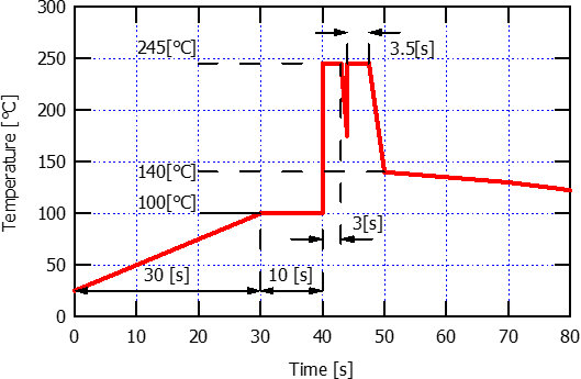
Recommended Reflow Soldering Profile

| Minimum | Recommendation | Maximum | Unit | |
|---|---|---|---|---|
| Ramp-up rate to preheat 25℃ to 150℃ | – | 2 | 2.5 | K/s |
| Preheat temperature | 150 | 150 | 160 | ℃ |
| Ramp-up rate to preheatb150℃ to 250℃ | 1.4 | – | – | K/s |
| Peak Temperature | – | – | 250 | ℃ |
| Time above 150℃ | – | – | 110 | s |
| Time at peak Temperature | – | – | 5 | s |
| Ramp-down rate | – | 3 | 5 | K/s |