
780 nm is a near-infrared wavelength sitting right at the edge of the visible spectrum – essentially invisible to the human eye but easily detected by common silicon sensors. This makes a 780 nm LED an ideal light source for optical sensing systems – it yields strong detector response without producing distracting visible light. By pairing a near-infrared LED with a photodiode or even a photodiode pair, engineers can implement closed-loop feedback control that stabilizes the LED’s intensity and yields consistent reflectance or position measurements under varying conditions. Read on to learn why 780 nm infrared LEDs hit a sweet spot between visible and IR, and how to select lenses, drive electronics, and control strategies to get the best performance in industrial sensors, optical encoders, and lab instrumentation.
What is 780 nm light and where does it sit between visible and IR?
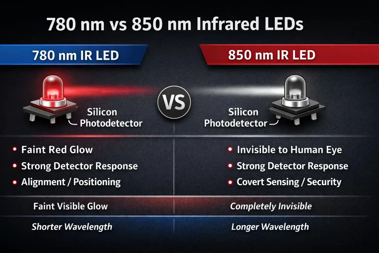

Figure 1: 780 nm vs 850 nm Near-Infrared Comparison
Side-by-side comparison showing how 780 nm and 850 nm infrared LEDs differ in visibility, silicon photodiode responsivity, and typical sensing use cases, highlighting 780 nm’s proximity to the visible edge and 850 nm’s deeper tissue and material penetration.
The 780 nm wavelength marks the transition between visible red light and the infrared (IR) spectrum. In fact, 780 nm is often considered the very start of the IR band, just beyond deep red visible color. Human vision effectively stops responding around 750–760 nm, so a 780 nm LED emits infrared 780 nm radiation that we cannot see. However, silicon photodiodes and other NIR detectors still respond strongly in this range, since their sensitivity typically spans roughly 400 nm to 1100 nm. This means a 780 nm LED can provide illumination that is “invisible” to people but very much visible to electronic sensors.
Because 780 nm lies so close to the visible range, optical components designed for visible light often work well at this wavelength. Standard glass lenses and optical coatings that transmit visible light will usually transmit 780 nm IR with minimal loss. For reference, Tech-LED categorizes 780 nm devices in its IR / NIR LEDs [internal link] range rather than the visible LED (400–800 nm) [internal link] range, since 780 nm is considered infrared. Likewise, wavelengths above about 1100 nm enter the short-wave infrared realm requiring specialized SWIR LEDs [internal link] and detectors (beyond the scope of this article). Compared to longer IR wavelengths, the 780 nm band also benefits from lower atmospheric absorption and scattering (similar to visible light), which can be useful in free-space sensing. (For a broader overview of LED wavelength categories from visible through IR, see our LED wavelength guide [[TODO_URL_WAVELENGTH_PILLAR:/blog/led-wavelength-guide/]] – [placeholder link].)
Why choose a 780 nm LED vs an 850 nm IR LED for optical sensing?
In designing an optical sensor, one might ask: why use a 780 nm LED instead of a more common 850 nm IR LED? The answer often comes down to application-specific requirements. Both 780 nm and 850 nm fall in the near-IR range and will drive strong responses in silicon photodiodes. However, a 780 nm LED has a slightly shorter wavelength, which means it sits closer to the visible threshold. In practical terms, a high-power 780 nm LED might exhibit a very faint deep-red glow when driven hard, whereas an 850 nm LED is essentially invisible. If an application benefits from a barely visible beam for alignment or safety indication, 780 nm can be advantageous; if complete darkness to the human eye is required, 850 nm may be preferable.
Another consideration is detector and filter optimization. Many off-the-shelf IR photodiode modules and receiver ICs (such as those in remote controls) are optimized for 850–940 nm wavelengths. Using a 780 nm source might require ensuring the photodiode or phototransistor has no built-in filter blocking shorter IR. On the other hand, 780 nm LEDs can leverage the very peak of silicon responsivity. According to photodiode data, silicon detector responsivity peaks around 900 nm (~0.6 A/W) and remains very high at 780 nm (on the order of 0.5 A/W). In other words, a silicon photodiode will generate nearly as much current from 780 nm light as it would from 850 nm light at the same power level. This excellent detector efficiency at 780 nm makes it attractive for sensing designs that want maximum signal levels.
There are also historical and supply considerations. The 780 nm wavelength has seen use in scientific and commercial devices (for example, early optical storage drives and certain spectroscopy instruments), so specialized suppliers have developed LEDs at this band. Niche scientific LED suppliers (such as Thorlabs in the lab instrumentation space) offer 780 nm LED emitters for researchers, highlighting the demand in scientific and metrology contexts. In contrast, 850 nm LEDs are mass-produced for consumer electronics and industrial sensors, often giving them an edge in price and availability. Engineers should weigh the cost and sourcing: a 780 nm LED may come from a specialty manufacturer at a higher price, but it could offer performance benefits for the intended sensor. (For a deeper dive into the uses of 850 nm IR LEDs, see our 850 nm LED cluster article [[TODO_URL_850:/blog/850-nm-led/]] – [placeholder link]. Likewise, for context on visible red emitters, see our 630 nm LED [[TODO_URL_630:/blog/630-nm-led/]] and 660 nm LED [[TODO_URL_660:/blog/660-nm-led/]] cluster articles – [placeholder links].)
How do silicon photodiodes respond at 780 nm, and what is a photodiode pair?
Silicon photodiodes are a natural companion to 780 nm LEDs. As mentioned, a silicon PIN photodiode’s spectral response covers the near-IR nicely – typically peaking around 850–900 nm and still around 80–90% of peak efficiency at 780 nm. In terms of absolute sensitivity, this corresponds to roughly 0.5 A/W responsivity at 780 nm for a typical photodiode, meaning 1 mW of 780 nm light yields about 0.5 mA of photocurrent. The key takeaway is that detectors will have no trouble “seeing” a 780 nm LED’s output. Moreover, because 780 nm is just outside the visible band, any standard silicon photodiode (without an intentional visible-light cutoff filter) will detect it – no exotic materials needed (unlike mid-IR or far-IR detectors).
The term “photodiode pair” in this context often refers to using two photodiodes in tandem for improved measurement accuracy and stability. One common configuration is a reference and measurement photodiode pair. Here, one photodiode is positioned to monitor the 780 nm LED’s output directly (a reference beam or back-facet monitor), while the second photodiode measures the light after it interacts with the target (for instance, reflected from a surface or passed through a sample). By comparing the two signals or using the reference to normalize the measurement channel, the system can compensate for variations in LED output, detector drift, or ambient light. This dual-detector setup effectively cancels out noise: if the LED’s intensity fluctuates or slowly declines with temperature, the reference photodiode catches it and the control system can adjust or calibrate the reading accordingly. In closed-loop arrangements (discussed further below), the reference photodiode’s current can even feed back to actively control the LED drive, keeping output constant. Overall, at 780 nm the photodiode pair approach works particularly well because the LED’s emission and the photodiodes’ peak sensitivity align, maximizing signal-to-noise for both reference and sensing channels.
IR LED fundamentals: spectrum, emitter behavior, and intensity control
A 780 nm LED is an infrared light emitting diode, and it shares many fundamentals with any LED. It is a semiconductor emitter that releases photons when driven by a forward current. The difference is the semiconductor material and bandgap are chosen such that the emitted light has a peak wavelength around 780 nm (deep red/IR range). Unlike a laser, an LED produces a relatively broad emission spectrum – typically with a bandwidth of 20–30 nm for near-IR LEDs. That means a “780 nm LED” might emit photons from roughly 760 nm to 800 nm, centered on 780. This broad spectrum can be beneficial for some sensor designs, as it is less sensitive to precise wavelength shifts and can simplify optical filter design (a filter can catch the whole LED spectrum).
In terms of electrical behavior, infrared LEDs follow the same diode equation as other LEDs. The forward voltage is low – usually around 1.2 to 1.5 V at nominal currents for a GaAlAs or similar 780 nm diode. They are current-driven devices, so intensity is controlled by adjusting the drive current. More current leads to higher optical output (until saturation or thermal limits). The relationship is roughly linear over a range, though at high currents efficiency droops and heating can reduce light output. Intensity control can be done in continuous (DC) mode or by pulsing the LED. For sensor applications, pulsed operation is common: you can emit brief intense flashes of IR light and synchronize the photodiode reading to those pulses. This not only allows easy control over the light level (via duty cycle) but also helps with ambient light rejection when combined with synchronous detection. Importantly, because 780 nm LEDs emit no visible light, all optical measurements must use radiometric units (power, irradiance, etc.) rather than photometric units. An optical power meter or calibrated photodiode is used to quantify output, since photometric “lumen” measurements apply only to visible light. In short, designing with a 780 nm LED involves treating it like any LED – manage the current to control light, and be mindful that you’re working in radiant flux (milliwatts of IR) instead of lumens.
Optical design considerations: lens selection, beam angle, and spot size
The optical design around a 780 nm LED can greatly influence sensing performance. Key factors include the lens, emission angle, and resulting spot size on the target or detector. Many IR LEDs come in packages with built-in lenses (for example, a molded epoxy dome or a flat window). These dictate the native beam angle – common options are around 60 degree or 120 degree half-angles for standard LEDs. A wider beam (e.g. 120°) spreads the light, useful for short-range diffuse sensing or when covering a broad area, but it lowers the intensity on any one spot. A narrower beam (e.g. 20–60°) or a collimated output concentrates the IR light, which can greatly improve the signal at a photodiode receiver, at the cost of needing more precise alignment.
Engineers should choose lens and beam angle based on the application’s geometry. For a reflective sensor measuring a small target, a narrow beam that just covers the target area will improve accuracy and reduce stray reflections. Conversely, for an encoder wheel with slits, a slightly wider beam might ensure the LED illuminates the sensor through each slit without requiring perfect alignment. If an extremely tight beam is needed, secondary optics or an external lens (often glass) can be employed in front of the LED. Glass or high-quality acrylic lenses are usable since 780 nm light passes through glass similarly to visible light – AR (anti-reflective) coatings tuned to visible can still be effective at 780 nm. Using a well-focused lens can create a defined spot (for example, a 5 mm spot at a certain working distance), which can be critical for repeatable measurements. It’s also worth considering the LED’s package: some high-power IR LED modules have integrated glass windows or lens caps that can handle more heat and maintain clarity better than plastic at high irradiance levels. In summary, optimize the beam angle and optics so that the IR light illuminates only what you want to measure, with sufficient intensity and minimal spillover.
Ambient-light rejection: modulation, synchronous detection, and filtering
Ambient light – from sunlight to factory lighting – can be a major source of interference for optical sensors. At 780 nm, both the sun and common artificial lights (especially incandescent or sunlight through windows) can contribute background IR. To ensure reliable sensing, designs should include ambient-light rejection techniques. One of the most effective methods is modulation of the LED. Instead of emitting a steady IR beam, the 780 nm LED is rapidly pulsed or driven at a specific frequency (for example, tens of kHz). The photodiode receiver circuit is then tuned to that frequency, using techniques like lock-in amplification or band-pass filtering to ignore steady or off-frequency light. Modulating the LED output in the 10–100 kHz range lets the receiver discriminate the signal from DC ambient illumination – in essence, the sensor “listens” only to the 780 nm LED’s blinking pattern and rejects constant sunlight or 50/60 Hz lighting hum. This synchronous detection approach dramatically improves immunity to ambient noise and allows the sensor to work in bright environments.
Optical filtering is another layer of defense. A photodiode used with a 780 nm LED can be fitted with an IR band-pass filter or a long-pass filter that cuts off visible light. Many IR photodiodes come in packages with a built-in daylight filter (often appearing as a dark or black tint) that blocks wavelengths below ~750–800 nm. This means the photodiode is mostly blind to visible light but fully sensitive to the 780 nm LED’s emissions. When selecting such filters, ensure they indeed transmit at 780 nm (since some “IR” filters might be centered around 850+ nm and could attenuate 780 nm slightly). Additionally, designing the sensor with physical separation or baffling between the LED and photodiode helps reduce direct optical crosstalk and lets the modulation/demodulation scheme do its job on true signal. Some systems even use a second “ambient” photodiode (not exposed to the LED, only ambient) to subtract out background light in real time. By combining optical filtering, physical design, and electronic modulation techniques, a 780 nm sensing setup can achieve excellent ambient light rejection for consistent performance indoors or outdoors.
High-power 780 nm LED packages: SMD, COB modules, SMBB, and EDC
For applications that demand more IR light, whether to cover longer distances, illuminate larger areas, or overcome high background noise, there are high-power 780 nm LED packages available. Unlike a standard 5 mm through-hole LED with limited drive current, high-power emitters use advanced packaging and thermal management to handle higher currents and dissipate heat. Surface-mount device (SMD) packages are common for mid- to high-power IR LEDs, offering a low-profile form factor that can be soldered to a PCB with proper thermal pads. Tech-LED’s own SMBB series [internal link] and EDC series [internal link] are examples of high-power IR LED components in surface-mount packages. These use robust lead-frame or ceramic substrates to allow higher drive currents (hundreds of mA up to 1 A or more per LED) and often feature integrated lenses or windows.
Another route to high output is the chip-on-board approach. COB modules [internal link] at 780 nm mount multiple LED chips together on a thermally conductive board, effectively creating a single powerful IR light source. By combining many emitter chips, COBs can deliver very high radiant flux (in some cases tens of watts of IR output) while still being driven at safe currents per chip. For instance, a COB module might integrate an array of 780 nm dice to reach the equivalent of a 50 W or even 100 W class IR illuminator (essentially a 100 watt IR source) – essentially a high power LED source – when properly cooled. These solutions come with trade-offs: more complex heat sinking, and often a larger emitting area (which can affect how easily you can collimate the beam to a tight spot). Nonetheless, for tasks like large-area reflective sensing or long-range break-beam sensors, high-power LED assemblies ensure you have ample infrared light to get a strong detector signal. When choosing a high-power package, consider the “out of the box” beam pattern (COBs typically emit a wide flood of light unless paired with secondary optics) and ensure the package can be integrated mechanically into your system (SMD and COB packages will require mounting to a board or heat sink). High-power 780 nm LEDs have opened up applications that were once limited to infrared lasers, providing a safer, lower-cost technology for intense IR illumination.
Electrical design: voltage, current drive, and thermal management
Driving a 780 nm LED requires careful attention to electrical and thermal design – especially for high-power versions. Like all LEDs, these IR emitters are current-driven components. A constant-current driver is recommended to regulate the LED current regardless of supply voltage fluctuations. For example, if you are using a 780 nm LED in a sensor product, you might include a dedicated LED driver IC or a simple current-regulating circuit (such as an op amp or transistor with sense resistor) to supply a steady forward current. The forward voltage of a 780 nm LED is relatively low (~1.3 V), so multiple LEDs can be placed in series if a higher voltage supply is available, but you must ensure each LED in the string shares current equally (usually not an issue if they’re identical and thermally linked).
Thermal management is crucial once you drive significant current. Any LED converts a portion of electrical power into light and the rest into heat. Infrared LEDs can be quite efficient, but even a high-power LED with 30–40% efficiency at converting current into IR light will dissipate 60–70% of the input power as heat. For instance, an LED driven at 500 mA and 1.3 V forward drop uses 0.65 W of power, and if 0.2 W becomes IR output, about 0.45 W is heating the junction. Without proper heat sinking, the junction temperature will rise, leading to decreased output and potential failure. Therefore, use the metal pad on an SMD or the base of a COB to conduct heat to a thermal plane or external heat sink. Materials with high thermal conductivity (copper planes, aluminum substrates, etc.) should be employed. Also consider that at higher junction temperatures, the LED’s wavelength can shift slightly (a few nm) and efficiency drops – another reason to keep it cool if you need stable intensity and wavelength.
In terms of protection and longevity, it’s wise to include a series resistor or active driver that prevents current surges (for example, when first powering on, or if there are inductive transients in the system). Additionally, because 780 nm is outside the visible range, an LED that is “on” at full power won’t have the obvious visible brightness cue that a red LED would – so always double-check with instruments that your current is what you expect. You might integrate a test photodiode or use a multimeter in a safe test mode to verify the LED output during development. Overdriving an IR LED can cause immediate damage or gradual degradation (aging) that reduces output over time. By adhering to recommended drive currents, managing heat, and providing stable supply conditions, you ensure the LED will perform reliably for the lifetime of the product.
Calibration and measurement: radiometric vs photometric units and reference intensity
When working with a 780 nm LED, it is important to calibrate and measure its output using the correct units and instruments. Because this wavelength is beyond human vision, photometric units like lumens or lux (which are weighted to the human eye’s response) are essentially meaningless here. In fact, at 780 nm the eye’s luminous efficacy is near zero, so a standard lux meter would register almost no “brightness” even if the LED is radiating significant power. Instead, engineers use radiometric measurements: radiant flux (watts of optical power), irradiance (W/m² on a surface), or radiant intensity (W/sr from a source). As noted earlier, radiometric measurements represent real optical energy (watts) independent of human vision. Practically, this means using a calibrated photodiode sensor or an optical power meter to measure the 780 nm LED’s output. Silicon photodiode power sensors can be calibrated at 780 nm and will give readings in milliwatts. If needed, you can convert these to an equivalent photometric unit for comparison by applying the photopic response curve (but again, at 780 nm the conversion factor is extremely low, so it’s usually not done).
Calibration of the LED in a sensing system might involve setting a reference intensity. For example, you might drive the LED at a current that produces a known irradiance at the photodiode (say, 1 mW/cm² on the target area). This could be established during manufacturing by adjusting the drive current until a reference sensor reads the desired value. Some systems include a feedback calibration step on power-up: the LED briefly illuminates a reference target or an internal reference photodiode, and the controller tweaks the output to hit a setpoint. It’s also important to consider long-term calibration – LEDs can dim over time (especially if overdriven or run hot). Using the aforementioned photodiode pair or closed-loop control can maintain consistent output despite aging. Radiometric calibration ensures that your measurements (like a distance reading from a reflective sensor or an optical density measurement in an instrument) remain accurate. Always document the reference conditions (distance, geometry, target reflectance) for your calibration so that field measurements can be interpreted correctly. By using radiometric units and periodic reference checks, you avoid the pitfalls of trying to treat an IR source with “lumens” and instead maintain a solid physical basis for your sensor’s performance.
Closed-loop control architectures: photodiode feedback for stable LED output
One of the powerful techniques in optical sensing design is closed-loop control of the LED output using photodiode feedback. In a closed-loop (also known as Automatic Power Control in laser terms), the aim is to keep the LED’s emitted intensity constant even as environmental or device conditions change. At 780 nm, where precision measurements are often the goal, this can be crucial. The basic architecture involves a monitor photodiode that receives a fraction of the LED’s light (either through a beamsplitter, a leakage through a semitransparent mirror, or simply from the LED’s back emission if using a package that allows that). This photodiode is wired into a feedback circuit – typically an op amp or dedicated LED driver – that adjusts the LED’s drive current to maintain a target photodiode current. Since the photodiode current is proportional to the LED’s optical output, the loop effectively regulates the optical power.
For instance, if the LED’s output starts to drop due to heating, the photodiode current falls, and the feedback loop responds by slightly increasing the LED drive current to compensate, bringing the output back up. Conversely, if the LED output rises (perhaps due to a supply fluctuation or a drop in temperature), the circuit will dial back the current. According to a TI application note describing photodiode-feedback LED control loops, the loop will close and maintain the correct drive so the photodiode current (and thus light level) stays constant. In practice, this might be implemented with an op amp in a transimpedance configuration: the photodiode feeds back into the op amp such that the LED current is continuously adjusted to hold the photodiode at a set reference voltage (the setpoint corresponding to desired light output). The result is a highly stable illumination source. In a sensor, this means the LED is no longer a major source of drift – any measurement changes are more likely due to the actual sensing target, not the LED output wandering.
Using photodiode feedback does introduce complexity: you need an extra photodiode component, calibration of the setpoint, and careful design to avoid loop oscillations (bandwidth compensation capacitors are often needed to keep the feedback loop stable). But the benefits in precision applications are significant. Many analytical instruments and high-end optical encoders incorporate this closed-loop LED control. It essentially gives you the stability akin to a regulated laser source but with the safety and simplicity of an LED. For 780 nm systems, where you might be aiming for very consistent reflectance readings or maintaining the same illumination over months and years, closed-loop control is a smart design choice. Just remember to also consider safety – if the feedback loop tries to overdrive the LED to maintain output (for example, as the LED ages), it could shorten the LED’s lifespan. A well-designed system will include current limiters and perhaps an end-of-life indicator once the LED requires too much current to maintain the set output (signaling that the LED should be replaced or that the product has reached its intended operating life).
Applications and examples: optical encoders, reflectance sensors, and lab instrumentation
780 nm infrared LEDs find use in a variety of sensing and control applications, especially where an “invisible” but detector-friendly light source is needed. One prominent example is the rotary or linear optical encoder. In an optical encoder, an IR LED shines through or reflects off a patterned code wheel or scale, and photodiodes on the other side (transmissive encoder) or next to the LED (reflective encoder) detect the light interruptions. Most optical encoders use infrared LEDs as the light source with matched photodetectors. While 850 nm is common, 780 nm can be used in encoders that require compatibility with certain detector types or where slightly shorter wavelength might improve the resolution with certain diffraction gratings. The benefit of IR in encoders is that it produces no visible light to interfere with operators, yet the photodiode array picks up a clear signal as the wheel turns. High-resolution encoders sometimes even employ laser diodes at similar wavelengths, but LEDs offer a cheaper and safer alternative for many industrial motion control systems.
Another application area is reflective sensors – for instance, those used in automation to detect object presence, color marks, or surface conditions. A 780 nm LED paired with a photodiode can serve as a reflectance sensor that measures how much IR light bounces back from a target. Because 780 nm is near IR, it tends to penetrate a bit into materials (like paper, plastics) differently than shorter visible wavelengths, which can be advantageous for certain sensing tasks (for example, moisture content or dye presence might show contrast in IR that isn’t visible in white light). Also, using IR avoids adding visible glare or altering the appearance of the target. In lab instrumentation, 780 nm LEDs are sometimes used for absorbance measurements in spectrophotometers or as reference light sources. For example, a scientific instrument might use a 780 nm LED to illuminate a sample cuvette and measure how much light is transmitted vs absorbed, with the photodiode reading indicating the sample’s properties. The choice of 780 nm can be because it’s outside the visible range (so it doesn’t cause fluorescence in samples not intended to fluoresce, and it doesn’t interfere with vision-based observations), yet it’s still within the sensitivity range of standard silicon detectors and easy to generate with an LED. Additionally, some fluorescence or Raman spectroscopy setups use 780 nm as an excitation or reference wavelength (though lasers are more typical there, high-power LEDs have started to appear in certain analytical devices for cost reasons).
It’s worth noting that any application that could use a deep red 660 nm LED might also consider 780 nm if invisibility is preferred, as long as the sensor can accommodate it. For example, a safety light curtain in a factory could use 780 nm LEDs and photodiodes to create an invisible “tripwire” grid. Similarly, IR illuminators for security cameras sometimes include wavelengths like 730 nm or 780 nm to balance having some residual visibility (for alignment) with mostly covert lighting. The 780 nm LED is quite versatile – from encoder disks to lab-on-chip devices – offering a unique blend of near-visible behavior and pure IR stealth. Engineers can pick this wavelength when they need that blend of properties to solve a sensing challenge.
780 nm LED selection checklist: performance, price, and supplier considerations
When selecting a 780 nm infrared LED for your project, keep the following considerations in mind:
- Performance requirements: Determine the optical power needed at the detector. Choose an LED (or LED module) that can supply that radiant intensity with some margin. If your application requires a focused beam or long range, consider high-power packages or multiple LEDs and ensure the beam geometry fits your design.
- Beam angle and optics: Check the native emission angle of the LED package. If a specific spot size or coverage is required, you might need an LED with an integrated lens or plan for adding external optics. Verify that any built-in lens can handle your needed range (e.g., a narrow beam for an encoder vs. a wide beam for a proximity sensor).
- Thermal and electrical specs: Review the forward voltage and maximum current. Ensure your driver circuit can supply the current and that you have a suitable constant-current source. Look at thermal resistance in the datasheet – do you need a heat sink or special PCB layout to dissipate heat? Designing the PCB with thermal vias or using metal-core boards might be necessary for high-power LEDs.
- Photodiode pairing: If using a photodiode from Tech-LED’s photodiode lineup [internal link] or another supplier, confirm its sensitivity at 780 nm. In most cases silicon is fine, but ensure any filter on the photodiode passes 780 nm. If you plan to use a reference photodiode for feedback, some LEDs come with a monitor diode in the package (more common in laser diodes, but worth checking if needed).
- Price and availability: Because 780 nm LEDs are somewhat specialized, prices can vary more than standard IR or visible LEDs. Get quotes from a reliable supplier – you may find that a high-power 780 nm LED from a niche manufacturer costs more per unit than a mass-market 850 nm LED. Consider future supply chain stability; ensure the manufacturer has this wavelength in regular production so you’re not left with obsolete parts.
- Manufacturer and support: Work with a manufacturer or supplier who has expertise in infrared LED technology. A specialized IR LED manufacturer can provide guidance on using the product, share detailed spectral and degradation data, and even offer custom options (for instance, custom lensing or emitter arrays) if your application demands it. You’ll want a partner who stands behind the product with documentation and potentially a product datasheet (see below).
- Safety and compliance: Remember that 780 nm output, while invisible, is still optical radiation. Ensure that your design complies with relevant safety standards (such as IEC 62471 for lamp/LED safety). High-power IR LEDs can pose an eye hazard because the eye won’t blink or avert from invisible light. Implement appropriate enclosures or interlocks if needed, and label the device per regulatory requirements (in many cases 780 nm LEDs will be classed as “Exempt” or Class 1 if power is low, but it’s your responsibility to verify).
- Integration and testing: Plan for how the LED will be mounted and calibrated in your system. For example, will you need to fine-tune its orientation to align with a photodiode? Will you perform a calibration step to adjust LED current for a standard output level? It’s wise to procure a few extra units for prototyping and testing under real conditions (temperature extremes, ambient light, etc.) to ensure the 780 nm LED meets all expectations in situ.
By checking each of these points, you can confidently select and integrate the right 780 nm LED source for your optical sensing or control project. With proper implementation, a 780 nm infrared LED can provide a robust, precise, and practically invisible illumination that drives your sensor solution effectively.


