
Infrared LEDs at the 940 nm wavelength emit near-infrared light that is invisible to the human eye, making them ideal for gesture recognition and proximity sensing applications where illumination must be covert. Unlike shorter-wavelength IR emitters (e.g. 850 nm) that produce a faint red glow, a 940 nm LED is completely invisible to the naked eye. This allows engineers to integrate IR-based gesture and proximity sensors into devices without disturbing users or revealing the sensor’s presence. By pairing a 940 nm IR LED with a compatible photodiode or proximity sensor, designers can create a stable, invisible light source for detecting hand motions or nearby objects in machine-vision systems, consumer electronics, and security devices.
What defines the 940 nm infrared wavelength?
The 940 nm wavelength lies in the near-infrared (NIR) region, just beyond the visible red portion of the spectrum. Human vision generally stops at roughly 700–750 nm, so any LED emitting at 940 nm produces invisible infrared light (sometimes called “IR light”) that is virtually invisible to the human eye. In the context of LEDs, 940 nm refers to the peak emission wavelength of the semiconductor device. These IR LEDs typically have a narrow emission band (e.g. ±20–30 nm) around the 940 nm peak. This places them squarely in the NIR range (about 700–1000 nm), distinct from visible LEDs (400–700 nm) and from longer-wavelength IR like SWIR LEDs that emit beyond 1000 nm. For a broad overview of LED wavelength categories, see our LED Wavelength Guide which covers visible, NIR, and SWIR ranges.

Because 940 nm is a common wavelength for IR emitters, it has become a standard for many sensing technologies. The LED die materials (often GaAlAs or related compounds) are optimized to emit in the near-infrared. Importantly, the 940 nm output is invisible to the human eye under virtually any conditions – even at high drive currents, there is no visible glow. In contrast, an 850 nm IR LED will show a dim red glow when viewed directly in the dark (due to a small portion of its output creeping into the upper visible spectrum). This difference is critical for applications requiring total darkness or covert operation. Night vision systems and security camera illuminators, for example, often use 940 nm LEDs when they need to be completely invisible during operation. In summary, a 940 nm LED emits near-infrared light that is beyond human perception, yet can be readily detected by silicon-based sensors and cameras.
Why is 940 nm preferred for gesture and proximity sensing?
The 940 nm IR LED is preferred in gesture recognition and proximity sensing primarily because of its stealth and eye safety. Since the output is invisible to the human eye, using a 940 nm source means the device can shine IR light to detect hand movements or nearby objects without the user noticing any LED glow. This “covert” operation is highly desirable in consumer electronics – for example, smartphones use IR proximity sensors to turn off the screen when you hold the phone to your ear, and modern gaming systems or laptops may use IR LEDs for gesture sensors. In these cases, a visible or glowing LED would be distracting or aesthetically undesirable. A 940 nm LED provides the needed illumination for the sensor while remaining completely invisible (i.e. the IR illumination is invisible light only detected by the sensor, not the user).
Another reason 940 nm is favored is to avoid interference with ambient visible light. A proximity sensor that used, say, a visible LED or even a deep red LED could be affected by other light sources and would also be noticed by users. By operating in the near-infrared band, the sensor can leverage filters and modulation techniques (discussed later) to reject ambient light, enabling more reliable operation. Moreover, many off-the-shelf integrated proximity sensor modules (from companies like Vishay, Broadcom, ams, etc.) are designed around 940 nm emitters. Using the standard 940 nm wavelength ensures compatibility with these sensor ICs and photodiodes, which typically have peak sensitivity in the 900–950 nm range. In short, 940 nm IR LEDs hit a sweet spot: they are low-power and efficient emitters, invisible and thus covert for users, and they align well with the spectral response of common photodiode detectors in proximity sensor applications.
It’s worth noting that the 940 nm wavelength is a longstanding choice for IR remote controls as well – the classic IR remote for TVs and appliances uses a 940 nm LED to send data to a receiver. This is a testament to the wavelength’s balance of invisibility and detector sensitivity. A remote control’s super-bright 5mm IR LED can rapidly blink at 940 nm to carry signals, and the receiving photodiode (with a matching IR filter) picks it up easily. The user sees nothing, as the emission is invisible to the naked eye. The same principle carries over to gesture and proximity sensors: the system can flood a small area with 940 nm IR light and monitor reflections or interruptions without anyone being aware that light is being used.
940 nm vs 850 nm: invisibility versus sensor sensitivity
When comparing 940 nm IR LEDs to the other common NIR choice – 850 nm IR LEDs – the trade-off comes down to total invisibility versus maximum detector sensitivity and range. **What’s the difference?** An 850 nm LED emits a slightly shorter wavelength that silicon photodiodes and camera sensors detect very efficiently. In fact, typical CMOS sensors and silicon photodiodes have roughly twice the responsivity at 850 nm as they do at 940 nm. In practical terms, a security camera or photodiode will get a stronger signal (brighter image or higher photocurrent) from an 850 nm illumination than from a 940 nm illumination at the same power. This means an 850 nm IR illuminator tends to have a longer usable range for night vision or sensing – often on the order of 30–50% more range. For example, machine vision cameras might achieve ~18% quantum efficiency at 850 nm but only ~7% at 950 nm, so the 850 nm LED can produce a clearer image with less noise.
The disadvantage of 850 nm is that it is not completely covert: the LED die emits a small amount of deep-red light that is just barely visible in the dark, which can give away a camera's position. 940 nm LEDs are completely invisible under all viewing conditions, which is why 940 nm is chosen when total darkness is required, covert security, wildlife night-vision, and user-facing sensors, and why it's the better choice for illuminating a person's face or eyes (e.g. an IR facial-recognition flood illuminator), where any visible emission would alert or disturb the subject.
For the complete head-to-head, silicon quantum-efficiency figures, range and image-brightness trade-offs, daylight ambient-IR rejection, and a when-to-choose-which decision table, see our dedicated 850nm vs 940nm infrared LED comparison.
Notably, ambient conditions can also influence this choice. In outdoor sunlight, the background IR from the sun is very strong around 850 nm, whereas there’s a natural dip in solar IR energy in the 900–950 nm range. This means a 940 nm system might actually face less competition from sunlight (lower IR noise) compared to an 850 nm system. On the other hand, the camera sensor’s own sensitivity is lower at 940 nm. Engineers must balance these factors. In many cases, designers opt for 850 nm for raw performance (especially in dedicated IR illuminators for CCTV where a slight red glow is acceptable), and opt for 940 nm when invisibility or eye-comfort is critical (for example, IR lasers or LEDs used in eye-tracking and consumer devices often go with 940 nm to avoid any visible output).
It’s also worth mentioning that different applications may use other near-infrared wavelengths altogether. For instance, some medical and therapeutic devices use wavelengths like 810 nm or 850 nm in red light therapy for deeper tissue penetration (these near-infrared light sources are chosen for biological interaction rather than sensing). Those are different applications entirely – in sensing and imaging, 940 nm is chosen for stealth and compatibility with silicon detectors, whereas in therapy the goal is delivering NIR light to the body. In other words, 850 nm might appear in both security cameras and therapeutic LEDs, but 940 nm is almost exclusively used for optical sensing and communication purposes, not for things like red light therapy devices.
How do 940 nm IR LEDs interact with photodiodes and proximity sensors?
Infrared LEDs do not work in isolation – they are typically paired with a photodetector (such as a silicon photodiode or phototransistor) to create a sensing system. In a gesture or proximity sensor, the 940 nm LED serves as the IR light source, and the photodiode detects the IR light after it has either reflected off a target (for reflective sensors) or been interrupted (for break-beam sensors). The key is that the photodiode is selected or filtered to be sensitive to the 940 nm wavelength. Silicon photodiodes have an intrinsic spectral sensitivity that usually covers roughly 400 nm to 1100 nm, with a peak somewhere in the near-IR. In fact, many silicon photodiodes achieve peak responsivity around 900–950 nm. For example, a typical PIN photodiode might have its peak sensitivity (λp) at 940 nm, and a spectral response range of about 780 nm to 1050 nm. This aligns perfectly with a 940 nm LED emitter.
To improve the signal-to-noise ratio, these photodiodes often include an optical filter that blocks visible light and only passes IR. Common “dark glass” or epoxy packages on IR photodiodes serve this purpose – they look black to the eye but are transparent at ~800–1000 nm. Manufacturers specify this as a daylight-blocking or IR band-pass filter. For instance, Vishay’s BPV10 series photodiodes come in a black package with a filter matched to 850–950 nm IR emitters. By using a filtered photodiode, the sensor largely ignores ambient visible light (like sunlight or lamps) and focuses on the IR coming from the LED. The pairing of a 940 nm LED and a photodiode with peak sensitivity at 940 nm yields a very efficient system: most of the LED’s output lands in the photodiode’s most responsive range.
In operation, a proximity sensor will typically pulse the IR LED on and off (at say, 10–100 kHz or even up to a few MHz for time-of-flight sensors) while synchronously measuring the photodiode output. When an object or hand is nearby, the photodiode receives more IR light reflected back, or in a break-beam arrangement, the photodiode sees the LED’s beam when unobstructed and a drop in signal when something interrupts it. The use of a modulated IR light source and synchronous detection helps the system reject steady ambient IR (like sunlight) and just pay attention to the LED’s own contributions. Many integrated proximity sensor chips incorporate the LED driver and a photodiode in one package, simplifying this pairing. But even at the discrete component level, designing a 940 nm IR LED + photodiode setup is straightforward because of how common this wavelength pairing is – virtually all “IR receivers” (like those in remote-controlled appliances or IR sensor modules) are tuned for ~940 nm. In short, the IR LED provides the illumination and the photodiode converts the reflected or transmitted IR light into an electrical signal, enabling detection of gestures, presence, or distance.
A critical aspect of this LED-photodiode interaction is the geometry and alignment. The LED’s emission pattern and the photodiode’s field of view must overlap in the region of interest. In a gesture sensor, both the LED and photodiode are usually placed next to each other behind a single window, aimed in roughly the same direction so that the photodiode can catch light bouncing off a hand in front of the device. The effective range depends on the LED’s power and beam angle, the photodiode’s sensitivity, and the reflectivity of the target (a hand or object typically reflects only a fraction of the IR light). Advanced proximity and gesture sensors may use multiple LED+detector pairs at different angles to cover a wider area or to sense directional motion. For example, one LED could emit a wide infrared beam and multiple photodiodes at various positions measure the reflection intensity – by comparing signals, the system can deduce how a hand is moving across the field. Overall, the 940 nm LED and photodiode work in tandem: one emits invisible infrared light, the other detects it, and together with driver circuits or sensor ICs, they form a complete optical sensing loop.
Gesture-sensing fundamentals: reflectance, distance, and field of view
Infrared gesture sensing works by analyzing how IR light reflects off a moving hand or object. When a 940 nm IR LED illuminates the area in front of a device, any gesture (like a wave or swipe of a hand) will cause changes in the reflected IR signal that a photodiode can detect. There are a few fundamental parameters at play: reflectance (how much IR light the hand reflects back), distance (the further the hand, the weaker the reflection reaching the sensor), and the field of view of the system (how wide an area the IR illumination covers and the detector “sees”). Designing a robust gesture sensor means balancing these factors. The IR LED’s power and beam angle determine how large of a region is illuminated. For example, a narrow-beam LED can project a more intense IR spot on a target but covers a small area, while a wide-angle LED covers more area at lower intensity.
Most gesture recognition systems using 940 nm LEDs operate at relatively short range – typically within a few centimeters up to about 0.5–1 meter at most. This is because the IR reflection from a human hand diminishes with distance (following an approximate inverse-square law plus diffuse reflection losses). A simple one-LED, one-photodiode setup might reliably detect a hand wave at 10–30 cm. More advanced systems, sometimes employing multiple LEDs or camera-based IR sensing, can extend this range. Research prototypes have demonstrated that using only reflected 940 nm light and a photodiode, hand gestures can be recognized with high accuracy within about a 20–35 cm range. In one study, a 940 nm IR LED array was used to bathe a region in invisible light, and the variations captured by a photodetector allowed classification of gestures with up to 96% accuracy at roughly a 0.2 m distance. This underscores that even without a camera, IR reflectance differences over time can encode gesture information.
The field of view for gesture sensing relates to both the LED’s emission pattern and the photodiode’s acceptance angle. Many 5 mm through-hole IR LEDs have a half-angle around 20–30° (for example, a common 5 mm IR LED might have a ±24° emission cone). That means it produces a somewhat focused IR beam. If a wide gesture area is needed, designers can choose IR LEDs with wider beams (there are IR LEDs with 80° or 120° viewing angles), use diffusers, or deploy multiple LEDs. On the detection side, photodiodes often have a reception half-angle of around ±20–30° as well, though this can be widened with diffusive covers or by using multiple sensors. Essentially, the optical design needs to cover the interaction volume where gestures will occur. A narrow field of view can yield more range (since the IR energy is concentrated and the photodiode only “sees” a tight area), but it might miss gestures that occur off-axis. A wider field can capture more dynamic movements but at the cost of signal strength and possibly more ambient light interference.
Another aspect is ambient reflectivity – background objects can also reflect IR. A stationary background will create a steady baseline of IR return, whereas a moving hand creates a fluctuating signal. Gesture algorithms typically look for changes over time (AC signals) rather than absolute distance measurement, which makes them somewhat robust to static backgrounds. In summary, gesture sensing with 940 nm IR relies on the LED flooding the area with invisible IR and the photodiode measuring temporal changes in reflectance. By tuning the beam coverage (field of view) and ensuring sufficient IR intensity at the farthest intended distance, the system can reliably pick up gestures. The invisible nature of 940 nm IR ensures that these interactions happen without any visible cues – the user performs a hand wave in “thin air,” and only the device’s IR eye can see it.
Optical design considerations: beam angle, spot size, and coverage control
Designing the optical aspect of a 940 nm IR LED system is crucial for optimizing performance. Key considerations include the LED’s beam angle, the resulting spot size or illumination pattern, and how to control or shape the coverage. IR LEDs, like visible LEDs, come with various lensing options built into their packages. A standard 5 mm IR LED typically has a domed lens that focuses the IR output into a cone. For example, a “super-bright 5mm IR LED” used in remote controls might have a narrow beam (e.g. 20° half-angle) to maximize the forward intensity and reach a distant TV receiver. This essentially acts as an IR spot light, concentrating the infrared energy into a small spot so that even a low-power diode can transmit a signal across a living room. In contrast, a proximity sensor on a smartphone might use an SMD IR LED with a wide emission angle (60° or more) to create a broad illumination zone in front of the phone – a wider flood is better for short-range sensing so that if your face or hand is anywhere near the top of the phone, it gets lit by IR.
Controlling the beam and light distribution of a 940 nm LED can involve several tactics:
- Built-in LED Lenses: Many IR LEDs come with integrated lenses (either epoxy dome for through-hole or molded lens for SMD). Choosing a narrow-beam vs wide-beam LED at the component selection stage is the simplest way to set the coverage. Narrow lenses give higher radiant intensity (mW/sr) and longer reach; wide lenses give more coverage but less intensity.
- Secondary Optics: In some designs, additional lenses or diffusers are placed in front of the LED to shape the beam. For instance, one could use a small IR-transparent plastic lens to focus a wide LED into a tighter spot, or use a diffusive cover to spread a narrow beam. Materials like polycarbonate or acrylic are often used for IR optics (noting that they should have good transmission at 940 nm). A carefully designed secondary optic can tailor the IR light distribution to the exact area needed.
- Multiple Emitter Arrangements: Instead of one high-power LED, a design might use an array of several 940 nm LEDs pointing in slightly different directions to cover a larger field. This is common in IR illuminators for security cameras – you’ll notice LED illuminators often have multiple emitters in a cluster or even in a circular “ring light” configuration. Some high-power IR illuminator boards use dual row arrangements of LEDs (two concentric rings or two rows of emitters) to achieve both near-field and far-field coverage. One row of LEDs may have wide-angle lenses for broad, close illumination while another row has narrow optics for long-range spots. By mixing and matching beam angles, the overall system achieves both intensity and coverage.
The spot size produced by a 940 nm LED at a given distance is directly related to the beam angle. For example, with a ~20° half-angle LED, the full-width of the main beam (to first minima) might be ~40° – this would illuminate roughly a circular spot whose diameter grows with distance (approximately 0.7 times the distance). At 1 meter, that would be roughly a 0.7 m wide spot of IR. A 60° LED would create a much larger, more diffuse spot of about 1.15 m at 1 m distance, but with much lower intensity per unit area. Designers must ensure that the IR spot (or coverage pattern) matches the sensing zone of the photodiode or camera. If the IR spot is too tight and the user’s hand moves outside it, the gesture won’t be detected. If it’s too wide, you may waste IR power illuminating irrelevant areas (and also potentially collect more background noise).
In applications like machine vision or surveillance where IR illumination is used for night vision, beam control is also critical. IR LED illuminators for security cameras often come in variants like 30°, 60°, 90° beam spreads to match different camera lens fields of view. A narrow FOV camera (telephoto lens) gets a narrow IR spotlight to see far, while a wide-angle camera gets a wide IR flood. Here, high-power 940 nm LED arrays may be deployed, sometimes in SMBB or EDC high-power surface-mount packages or as custom COB modules. These allow many LED chips to work in unison, achieving powerful illumination that can be optically shaped as needed. The optical design ensures uniform light distribution in the scene and avoids hot spots or dark corners in the camera’s view. Ultimately, whether for a simple proximity sensor or a sophisticated IR lighting system, controlling the beam angle and coverage of a 940 nm LED is key to effective performance.
IR LED packaging: 5 mm, through-hole, SMD, and COB options
Infrared LEDs at 940 nm are available in a wide array of package types to suit different integration needs. The packaging influences not only physical mounting, but also optical output (through built-in lenses) and thermal behavior (for high power use). Here are the common package options:
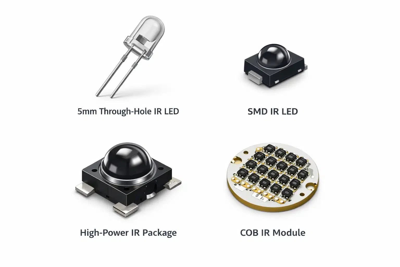
- 5 mm Through-Hole LEDs: These are the classic T-1 3/4 “bullet” style LEDs – a round epoxy lens of about 5 mm diameter, with two lead pins. They are often used in remote controls, hobby projects, and simple sensors. A super-bright 5mm IR LED typically can handle around 20–100 mA of forward current (some up to 100 mA continuous with proper duty cycle or pulsing). The epoxy lens can be clear or dark (filtered). As mentioned, the lens shape on these packages sets the beam angle (common versions are 20°, 30°, or even 45°). Through-hole IR LEDs are easy to use for prototyping and are very common – for example, the IR diodes in TV remote controls or alarm system sensors are usually 5 mm or 3 mm through-hole types. They are inexpensive and readily available in wavelengths like 940 nm. However, they are not ideal for high-density mounting or high-speed assembly, since they require manual placement or wave soldering on PCBs. Still, for one-off sensors or devices where a single IR LED is needed, a through-hole package works fine.
- SMD (Surface Mount Device) LEDs: For compact and mass-produced electronics, SMD IR LEDs are preferred. These come in various package styles – low-profile side-view LEDs for things like smartphones (which emit IR light from a side-facing window while lying flat on the PCB), top-emitting SMD LEDs in standard LED packages (like 0603, 1206 size outlines with clear encapsulant), or high-power SMD packages with metal pads for heat dissipation. SMD IR LEDs allow automated pick-and-place assembly. They can be quite powerful too: certain IR emitter SMD packages can handle >100 mA drive currents and incorporate internal lenses. An example is a “smd IR LED” in an automotive gesture sensor module which might be an SMT LED with a built-in lens to project IR forward. SMD packages make it easier to create arrays or clusters of IR LEDs, since they can be tiled on a PCB. Many modern IR illuminators or proximity sensors use SMD LEDs due to their small size and ease of integration.
- High-Power IR LED Packages: When significant IR output is needed (for instance, for long-range night-vision or machine vision illumination), high-power packages come into play. These include metal-backed LEDs like **SMB** packages (e.g. SMBB type from Tech-LED) which are surface-mount but with robust heat-sinking, or power LED packages that resemble tiny infrared flashlights (with multiple chips or a large single chip). There are also chip-on-board (COB) modules where many 940 nm LED chips are mounted together on a substrate, effectively acting as one large IR light source. COB modules can achieve very high radiant flux – even tens of watts of IR output – and often have their own lens assemblies. They might be used in professional IR illuminators (for example, an IR spotlight for a security camera that can illuminate 100+ meters in 940 nm).
- Custom Modules and “LED Strip” Assemblies: In addition to discrete components, manufacturers offer IR LED assemblies, like IR LED strip lights or bar modules. For instance, one can find 850 nm IR LED strips used for CCTV lighting (often a row of LEDs on a bar with resistors, ready to hook to 12 V). Similarly, 940 nm LED strips can be made for completely covert lighting needs – though 940 nm strips are less common due to the range trade-off, they exist for specialized applications. These typically involve dozens of small LEDs in a linear arrangement, sometimes advertised for use with night-vision cameras or DIY projects (some hobbyists use them with cameras for invisible room illumination). Another example of a module is the “IR illuminator board” found in security cameras: many are circular boards with 850nm or 940nm LEDs arranged in rings. Swapping to 940 nm LEDs in such a board would make the camera illumination invisible at the cost of some range. For prototyping, companies like Adafruit (a popular hobby electronics supplier) even provide breakouts with IR LEDs and drivers, making it easy to experiment with 940 nm sensing in Arduino or Raspberry Pi projects. These ready-made modules simplify the process of adding IR illumination to a project without dealing with individual LED soldering.
In any package selection, one should consider the forward voltage and current characteristics (covered next), as well as how the package’s lens and orientation suit the project. For example, a side-looking SMD might be great for a slim proximity sensor in a phone, but a 5 mm through-hole LED might be better for a discrete sensor that needs a narrow beam. Environmental factors matter too – if the device is used outdoors, you might need packages that are sealed or have known waterproof ratings (IP65+ enclosures, or potting). Often the LED itself isn’t the limiting factor for waterproofing (since you can always put a clear O-ringed cover over it in a product), but ruggedized IR LED modules are available for use in outdoor sensor systems. The bottom line is that 940 nm LEDs come in “all shapes and sizes,” from common through-hole diodes to advanced COB arrays, so engineers have a lot of flexibility in integrating them into different systems.
Electrical design: forward voltage, drive current, and power considerations
Designing the drive circuitry for a 940 nm IR LED is generally similar to other LEDs, but there are a few specifics to note. First, the forward voltage (VF) of a 940 nm LED is relatively low compared to visible LEDs. Typically, a small 940 nm LED might have a forward voltage around ~1.2 to 1.4 V at 20 mA (since infrared LEDs use low bandgap semiconductor materials). High-power IR emitters might have a slightly higher VF when driven at 100 mA or more, but it’s still on the order of 1.5–1.8 V, much lower than, say, a blue LED (~3 V). This low forward voltage means that if you are driving the LED from a higher-voltage supply (5 V or 12 V, etc.), you’ll need to account for the voltage drop difference (usually via a current-limiting resistor or a constant-current driver). Multiple IR LEDs can be placed in series more easily than visible LEDs due to the lower voltage drop, which is advantageous in making LED arrays (for example, you can string 6 or 7 IR LEDs in series on a 12 V supply, whereas you could maybe only put 3–4 visible red LEDs on the same supply).
The forward current rating of 940 nm LEDs depends on their package and die size. A standard indicator-style LED (5 mm package) is often rated for about 20 mA continuous, and can be pulsed at higher currents (e.g. 50–100 mA) if the duty cycle is low. Many IR remote control diodes are actually pulsed at 100 mA or more, but only for very short bursts (a remote’s data bits are short flashes, and the average current stays low). In proximity sensing, sometimes the IR LED is also pulsed to increase peak output without overheating. The key is to mind the average power. Speaking of which, power consumption should be managed especially in battery-powered devices: a continuously operating IR LED at 20–30 mA will draw a decent amount of power, so often the LED is off most of the time and only activated in bursts when taking a measurement. This is an example of a low-power design strategy – using duty cycling to get the needed performance while conserving energy.
In high-power IR illumination (like for cameras or floodlights), IR LEDs can be run at much higher currents, such as 100 mA continuous or even 1 A pulses, provided the package can handle the heat. Manufacturers will specify the maximum current (for instance, “100 mA continuous, 1 A pulsed (1% duty cycle)” as a typical spec for a high-power LED 940nm device). Exceeding these can cause the LED to overheat or the output to roll off. It’s important to use proper current-driving circuits – constant current regulators or drivers – to maintain stable output. Because IR LEDs don’t provide visual feedback (you can’t see if they get brighter or dimmer), designing a reliable driver and perhaps including a photodiode feedback (in critical systems) can ensure consistent IR light output. In some proximity sensor ICs, the chip will actually adjust the drive current to compensate for ambient conditions or target distance, effectively controlling the IR LED’s brightness on the fly.
From an electrical standpoint, one also considers the rise/fall time of the LED if using modulation. Most IR LEDs have fast response (capable of tens of MHz bandwidth), so turning them on and off quickly isn’t an issue – the limiting factor is usually the driver transistor or FET and the capacitance of the LED. Simple driver circuits often involve a transistor to sink current through the LED from a microcontroller’s output, or dedicated LED driver ICs for more precise control (especially if modulating at high frequency for time-of-flight measurements). Also note that because the forward voltage is low, if using a simple resistor, the resistor will drop most of the voltage – it’s often better to use a transistor-based constant current source to improve efficiency, especially for higher currents.
In terms of power consumption, an IR LED’s efficiency (radiant output vs electrical input) can vary. They might be, say, 20–30% efficient at converting electricity to IR radiation (the rest becomes heat). They don’t waste energy on visible light, which is good, but you still need to dissipate heat for high-power usage. If you drive many LEDs or a COB at significant power, pay attention to thermal design (covered in a later section). Lastly, ensure any driving circuit accounts for the temperature coefficient of the LED’s forward voltage – as the LED heats, VF drops slightly, which can lead to increased current if using a fixed resistor. A constant-current driver negates this concern. Summing up: know your LED’s forward voltage (~1.3 V region for 940 nm), set an appropriate drive current (whether it’s 10 mA for a tiny sensor or 500 mA for an illuminator), and manage the duty cycle to balance performance and longevity.
Ambient light rejection and noise suppression in IR sensing
One of the challenges in any IR sensing system (especially using 940 nm, since it’s close to sunlight wavelengths) is dealing with ambient IR noise. Ambient light – such as sunlight, incandescent bulbs, or even fluorescent lamps – contains infrared components that can swamp the photodiode’s signal. Without precautions, a proximity sensor in sunlight might think it’s constantly “seeing” something due to the sun’s IR, or a gesture sensor under certain indoor lighting might get false triggers. Therefore, successful IR sensor design incorporates strategies for ambient light rejection and noise suppression:
- Optical Filtering: As mentioned before, using an IR band-pass filter on the photodiode that only passes, say, 800–1000 nm greatly reduces out-of-band light. Sunlight is broad spectrum, but by filtering out visible and some IR outside the LED’s emission band, you narrow what the sensor responds to. Many integrated sensors have an optical filter or use a photodiode that inherently ignores visible light (via semiconductor design).
- Modulation and Synchronous Detection: This is the most powerful technique. The 940 nm LED is pulsed at a specific frequency (e.g. 10 kHz or 38 kHz or even higher). The detector circuit or IC then uses a band-pass filter or lock-in amplifier technique tuned to that frequency, ignoring steady DC light. This way, ambient sunlight (which is fairly constant or changes slowly) is seen as a DC offset and is filtered out, while the quickly modulated LED signal stands out. Most IR remote receivers, for example, use a 38 kHz modulation – the remote’s 940 nm LED blinks at 38 kHz, and the TV’s IR receiver module specifically listens for IR blinking at that frequency, effectively rejecting ambient IR from lamps or sunlight. Similarly, a proximity sensor might emit short bursts and sample the photodiode right after, subtracting a baseline (sample-and-hold of ambient) to cancel ambient interference.
- Ambient Calibration: Some systems take an initial reading with the IR LED off to measure ambient light, then turn the LED on and take a reading, and use the difference. This way, any ambient contribution can be subtracted out. This approach is common in proximity sensor ICs: they alternate between IR-off and IR-on measurements to cancel out background. It works well as long as the ambient light level isn’t changing super rapidly compared to the sampling rate.
- Shielding and Physical Design: The mechanical design can help too. By recessing the photodiode or putting a small tube (collimator) around it, you can limit the angles from which it receives light, thus possibly excluding some ambient sources. Also, placing the LED and photodiode close together and behind a common window ensures they “see” roughly the same ambient conditions, which helps if using subtraction techniques. An IR-transparent window that appears black can also block some higher wavelengths of light while passing 940 nm – for instance, some devices use a piece of smoked polycarbonate as a cover; it looks opaque but IR goes through. These windows sometimes have optical coatings to further attenuate visible light.
Interestingly, the choice of 940 nm itself can aid in ambient rejection under sunlight. The sun’s spectrum at ground level isn’t uniform – due to atmospheric absorption (mainly by water vapor), there’s a notable dip in solar irradiance around 940 nm. This means that at 940 nm, the continuous IR background from sunlight is somewhat reduced (roughly half of what it is at 850 nm). In other words, nature grants a bit of a ‘window’ for 940 nm where solar interference is lower compared to 850 nm. This can improve outdoor performance of 940 nm sensors in strong sun, partly offsetting the sensor’s own lower sensitivity at 940 nm. Some outdoor proximity sensors take advantage of this by operating at 940 nm to get better signal-to-noise on sunny days.
Nonetheless, extremely strong ambient IR (like direct sunlight on the sensor) can still be overwhelming. In critical systems, you might find additional measures like temperature sensors (to know if the photodiode is heating from sun) or algorithms that detect saturation and adjust thresholds. Noise suppression in IR sensing often also considers electrical noise – for instance, ensuring the transimpedance amplifier on the photodiode has low noise and maybe using multiple sampling to average out random noise. But the primary noise source in most cases is optical (photon shot noise from ambient light), hence the emphasis on optical and modulation techniques. By combining these methods – optical filtering, modulation/demodulation, baseline subtraction, and clever mechanical design – modern 940 nm IR sensors can achieve reliable performance even in the presence of significant ambient light. The result is that your device can sense gestures or proximity in a wide range of lighting conditions, from a dark room (where it only sees its own IR LED) to a bright outdoor setting (where it dynamically filters out sunlight to focus on its IR signal).
Machine-vision and security-camera use cases for 940 nm LEDs
Infrared LEDs, including 940 nm types, play a huge role in machine vision and security imaging when visible light is either undesirable or insufficient. In industrial machine vision, 940 nm LED lighting is used to illuminate inspection scenes without adding visible glare. For example, a factory might use 940 nm LED spotlights to inspect products on a line; cameras sensitive to NIR will pick up the illumination, but to any humans present, the lighting is dark, allowing them to work under normal (perhaps dimmer) visible lighting conditions. Additionally, IR light can sometimes reveal features that visible light cannot – certain inks, plastics, or surface defects have different reflectance in NIR. By using IR illumination, machine vision systems can enhance contrast for specific inspection tasks. Another benefit is that silicon-based cameras (CCD or CMOS) generally have extended sensitivity in the near-IR, so they can often be used with IR lighting simply by removing the IR-cut filter. Many machine vision cameras are sold as “NIR enhanced” versions for this reason.
In the realm of security and surveillance cameras, IR LEDs are ubiquitous. Most security cameras that advertise “night vision” have a ring of IR LEDs (either 850 nm or 940 nm) around the lens. At night, these LEDs turn on and flood the area with infrared illumination, allowing the camera to see in the dark (the camera switches to a monochrome mode with its IR-cut filter removed). The choice between 850 nm and 940 nm in these cameras is telling: 850nm LEDs are more common in consumer-grade cameras because they provide better range – the scene is brighter for the camera, although a faint red glow is visible on the camera if you look directly. 940nm LEDs are used in high-end or specialized cameras where stealth is important, such as wildlife observation cameras, military or police surveillance units, or certain indoor cameras where a red glow might be noticed and deemed bothersome. With 940 nm, the camera’s IR illumination is totally invisible, which can be critical for not tipping off people being monitored. The downside, as discussed, is reduced range – one rule of thumb is that 940 nm yields about 50% of the usable range of 850 nm under the same power, so you may need more LEDs or higher power to compensate.
One real-world example: some advanced outdoor security cameras use arrays of high-power 940 nm LEDs to achieve “no-glow” 0 lux surveillance. A case study described how a certain infrastructure monitoring camera incorporated 940 nm LED illuminators from a Japanese manufacturer to illuminate a perimeter without any visible output. The result was reliable night-vision footage that is completely covert – anyone looking at the camera sees just darkness, even though the area is brightly lit in infrared from the camera’s perspective. These kinds of systems often use dozens of 940 nm emitters (for instance, a cluster of 20–30 high-power LED dies behind optics) to reach the needed illumination levels at distance. Thermal management and driver design become important in such cases, since running so many IR LEDs at high power can generate significant heat.
Another use case bridging machine vision and medicine is eye tracking and facial recognition. Many modern devices (AR/VR headsets, driver monitoring cameras in cars, and phone face unlock systems) use 940 nm LEDs or VCSELs to illuminate the user’s face or eyes. The 940 nm is chosen because it’s safe and invisible – the user isn’t distracted by it. For eye tracking, small 940 nm LED lights (sometimes in the form of tiny infrared micro-LEDs or VCSEL arrays) are placed around the eyeglasses or headset frame; they shine IR on the eyes, and IR-sensitive cameras capture glint patterns to determine gaze. In facial recognition (like the dot projector in some phones), a 940 nm structured light pattern might be projected to map the face. Again, invisibility is key – the user just sees what looks like darkness, while the IR system does the work. And because 940 nm is friendlier to the eyes (no blink reflex triggered, and slightly lower energy photons than 850 nm), it’s a common choice for any application that actively shines IR at a person’s face. (Though note: “friendlier” doesn’t mean completely safe at high power – more on eye safety in the next section.)
Finally, beyond imaging, 940 nm LEDs also get used in certain specialty sensing systems. For instance, some agricultural NDVI imagers use NIR (around 850–940 nm) to assess plant health, and scientific instruments like IR spectroscopy devices can use LEDs in the 940 nm range as stable light sources. In communications, while fiber optics usually use 1310 nm or 1550 nm lasers, there are short-range IR data links (historically, IrDA in the 1990s used around 870–880 nm LEDs for a few Mbps over a meter or so). Modern iterations might use 940 nm for short, free-space optical links or eye-safe indoor communication. Even some night-vision goggles (though typically those rely on image intensifiers and any LED illuminator is usually 850 nm), if aiming for stealth, could incorporate a 940 nm flashlight to illuminate a scene covertly. In all these use cases, the unifying theme is that 940 nm provides a source of illumination or signaling that silicon sensors can see but humans (and most animals) cannot – a powerful capability for technology ranging from security to industrial automation.
Thermal, material, and enclosure considerations
When integrating 940 nm LEDs into a product or system, engineers must consider thermal management, material compatibility, and enclosure design, just as they would with any optical component. Here are some points to keep in mind:
- Thermal Management: High-power IR LEDs will generate heat. Although the photons at 940 nm carry less energy than visible photons, an LED converting electrical power to light (with maybe 20% efficiency) still dumps the other 80% as heat internally. If you drive an array of IR LEDs at significant currents (say a total of 5 W electrical input), you have ~4 W of heat to deal with. This can raise the LED junction temperature, affecting performance and lifespan. Just like visible LEDs, IR LEDs’ output can drop as they heat up (and wavelength might shift slightly). So use proper heat sinking – metal-core PCBs, aluminum housings, or active cooling if needed for very high powers. Keep junction temperatures within spec (often 100 °C max). Many IR LED products (like LED illuminators for CCTV) are built on metal-backed boards and encased in heat-dissipating housings to allow continuous operation at night.
- Material Transparency: Ensure that any lens, cover, or enclosure in front of the LED is transparent to 940 nm light. Common materials like polycarbonate, acrylic, or glass transmit 940 nm well (ordinary glass has high transmission for NIR up to about 2–2.5 µm). However, not all “clear” materials are equal: some plastics might have additives or tints that block IR. Conversely, some black plastics are actually IR-transparent (they appear black because they block visible, but they let IR through – often used for remote control windows). When designing an enclosed sensor, manufacturers often use a dark polycarbonate window over the LED/photodiode – it hides the components and blocks visible light, but it’s like a window for 940 nm. Check the datasheets or test materials for IR transparency. For instance, a piece of tinted glass with an AR coating could pass 940 nm efficiently but look opaque to us. Also, avoid materials that significantly fluoresce or absorb at NIR, as that could attenuate your signal. In short, the enclosure should be “invisible” to 940 nm radiation.
- Enclosure and Alignment: Mechanically, the LED and photodiode should be mounted and aligned properly relative to any windows or apertures. If the device is expected to meet certain waterproof ratings (like IP67 for outdoor use), the enclosure design might involve o-ring seals around an IR-transparent glass. Make sure sealing gaskets or potting compounds do not block IR – e.g. silicone potting can be quite transparent to IR, whereas some epoxy resins might not be. If the product will be outdoors, consider an enclosure that shields the sensor from direct sunlight at certain angles (to reduce false triggers), perhaps with a hood or sunshade, all while letting the intended IR signals in. Also consider contaminants: an IR sensor behind a window can get dirty (dust, mud, etc.), which will attenuate IR. Using oleophobic or hydrophobic coatings on the window can help keep it clean (as would a wiper or air purge in extreme cases).
- Eye Safety Considerations: While 940 nm LEDs are “eye-safe” at the low powers used in consumer devices (Class 1 LED product in most cases), high-power installations need to consider safety standards. Because 940 nm is invisible, a person won’t blink or turn away from a high-intensity IR source, which can lead to retinal exposure without awareness. Standards like IEC 62471 (for LED lamps) and IEC 60825-1 (laser safety, but often applied to high-output LEDs too) provide emission limits. For example, a single small 5 mm IR LED driven at typical currents is usually Class 1 (exempt) – not hazardous. But an array of 100 IR LEDs driving a narrow beam could potentially reach Class 1M or higher if viewed through optics. So, if you are designing something like an IR floodlight with 940 nm LEDs, ensure you understand the irradiance at certain distances and whether it could exceed safe limits. Sometimes the solution is simply to diffuse the beam more (so it’s not concentrated) or to implement an interlock (so it shuts off when someone could be too close). Using multiple lower-power distributed emitters rather than one highly concentrated source can also mitigate risk. In consumer products, manufacturers generally keep IR output well within safe limits – for instance, a phone’s face unlock IR flood is eye-safe at all viewing distances. Still, it’s a design consideration: invisible doesn’t mean harmless at very high powers.
- Longevity and Environmental Factors: 940 nm LEDs, like other LEDs, can gradually degrade in output over time especially if run hot. Ensure your design has margin such that even after, say, 5,000 hours of operation, there is enough IR output for the sensor to function (manufacturers often give an L70 lifetime for LED output). If your device will face temperature extremes, remember that LED forward voltage drops as temperature rises, and photodiode leakage currents increase with temperature – both can affect performance. Properly place temperature sensors or design compensation in if needed. Also, in very cold environments, the LED output might shift slightly in wavelength (though 940 nm devices will still be around that range). If the photodiode filter is extremely narrow, consider the wavelength shift with temperature. Most systems aren’t that hypersensitive, but it’s worth a check.
In summary, integrating a 940 nm LED-based system requires the same due diligence as any optoelectronic system: manage heat, use the right materials, design the enclosure for both performance and protection, and consider user safety. The good news is that because 940 nm LEDs are so widely used, many of these challenges are well understood and documented. Manufacturers of IR LEDs and sensors often provide application notes with recommended PCB layouts for thermal paths, suggested window materials, and formulas for calculating detection zones and safety distances. By following best practices, one can ensure that the 940 nm IR sensing solution remains robust and reliable under real-world conditions, whether it’s a proximity sensor in a dusty factory, a gesture sensor in a smartphone, or a covert IR illuminator on a perimeter fence.
Selection checklist for 940 nm LEDs in proximity systems
When selecting and designing with a 940 nm IR LED for a gesture or proximity sensing application, keep the following checklist in mind:
- Wavelength and Detector Match: Ensure the LED’s peak wavelength (~940 nm) is well-matched to the spectral response of your photodiode or sensor. Most silicon sensors are fine here, but double-check if using any unusual detector. A photodiode with peak sensitivity at 940 nm will give the best results.
- Optical Power and Range: Determine the required range (distance) for detection and choose an LED with sufficient radiant intensity. If you need only a few centimeters of range, a low-power LED at 20 mA may suffice. For longer ranges (30+ cm or more), consider higher-power LEDs or pulsing the LED at higher currents. Use narrow beam LEDs to extend range if needed, or multiple LEDs for coverage.
- Beam Angle vs Field of View: Choose the LED beam angle to cover the desired sensing area. For wide gestures, use a wide-angle LED or multiple emitters. Make sure the photodiode’s field of view aligns with the LED’s illumination cone. No blind spots in the interaction zone!
- Drive Circuit and Power Budget: Decide how you will drive the LED – via a simple resistor, a transistor driver, or a constant-current IC. Ensure the drive current is within the LED’s ratings (and consider peak vs continuous operation). Incorporate duty cycling if power consumption is a concern. For battery-operated devices, plan to keep the LED off when not actively sensing, to save energy.
- Ambient Light Handling: Plan for ambient IR. Will you use a optical filter on the photodiode? Will you modulate the LED and do synchronous detection? Verify that the sensor performance in a bright environment (sunlight, indoor lighting) meets requirements. You might need to adjust thresholds or provide shielding to achieve reliable performance under all conditions.
- Physical Layout and Materials: Position the LED and photodiode close together if possible for reflective sensing; this ensures they are looking at the same area. Use an IR-transparent window or lens if your product has a cover – test the window’s transparency at 940 nm. If the device exterior is subject to touching or dirt, consider a recessed or gasket-sealed window (with polycarbonate or glass) to protect the components. Ensure any indicator LEDs (visible light) on your product do not leak into the photodiode (some designs use a single cover for IR LED and status LED; be careful that a blinking visible LED doesn’t spoof the IR sensor!).
- Thermal and Eye Safety: If using more than a trivial amount of IR output, check the thermal implications. Provide copper pours or thermal vias under high-power LED packages. Consider worst-case ambient temperature – if the device might be in a hot car or under direct sun, will the LED overheat or current run away? Also consider eye safety classifications if your design is pushing a lot of mW of IR output in a tight beam. Typically, stay within Class 1 limits for consumer products, which usually isn’t a problem for low mA drivers, but be mindful if combining many LEDs.
- Regulatory and Interference: Verify if there are any regulatory guidelines (for example, some IoT products using IR might need to avoid interference with other sensors – IR can interfere with IR communication of other devices). Also, if this is going into a product that needs certification (like certain safety sensors), ensure the 940 nm LED and photodiode meet any relevant standards (e.g. IEC 60747 for photodiodes or IEC 62471 for lamp safety as mentioned).
By going through these points during design and component selection, you can significantly de-risk your 940 nm IR sensing project. In essence, you want to choose the right LED (wavelength and output) and drive it appropriately, pair it with the right detector and optical setup, and protect the system from environmental factors. 940 nm IR LEDs have proven themselves in countless proximity sensors and gesture recognition systems – with this checklist, you can leverage their benefits (invisibility, reliability, and compatibility with silicon sensors) while avoiding common pitfalls. Happy designing with invisible light!
What is a 940nm led and how does the 940nm wavelength affect performance?
A 940nm led is an infrared led that emits light at the 940nm wavelength in the near infrared range. Because this wavelength is beyond visible red, 940nm infrared light is less detectable to the human eye and to many cameras without infrared sensitivity, which makes 940nm ir leds popular for discreet night vision applications. Performance-wise, 940nm infrared leds generally produce less apparent intensity than 850nm ir variants for the same electrical drive, so designers often use more diodes or higher current. Efficiency and viewing distance depend on LED die quality, optics, and thermal management; highly efficient 940nm infrared led light modules can still provide effective illumination for specific night vision devices and surveillance systems.
How does 940nm leds compare to 850nm infrared and 850nm ir led strips?
940nm leds and 850nm infrared LEDs both operate in the near infrared band, but 850nm infrared light tends to appear as a faint red glow to the naked eye, while 940nm infrared is essentially invisible. 850nm ir led strips are commonly used where greater effective range and camera sensitivity are prioritized, because many sensors are more responsive around 850nm. For covert operations or minimizing visible glow, 940nm ir leds are preferred even though they can be slightly less efficient and may require more elements to match the illuminance of 850nm options.
Can 940nm infrared led light be used with night vision devices and night vision applications?
Yes. 940nm infrared led light can be used with many night vision devices and night vision applications, particularly digital cameras and CMOS/CCD sensors that are sensitive in the near infrared band. While traditional image intensifier tubes may perform better with 850nm, modern night vision cameras often detect 940nm effectively. When designing for night vision, consider the device sensitivity curve, desired range, and whether a covert (non-glowing) solution is required.
Are 940nm ir leds safe for skin exposure compared to red light therapy and white light?
Infrared LED emission at 940nm is non-ionizing and generally safe for incidental exposure, but it is not intended for red light therapy, which typically uses visible red (e.g., 630–660nm) or near-infrared around 810–850nm for therapeutic effects. White light is broad-spectrum visible illumination and has different safety considerations. For prolonged or deliberate exposure to high-intensity infrared sources, follow manufacturer safety guidelines and avoid direct eye exposure since infrared can be damaging without visible warning.
How do ir led strip light and led strip lights using 940nm perform in terms of range and efficiency?
ir led strip light products using 940nm can provide effective short- to medium-range illumination depending on emitter power, lensing, and array density. Compared to 850nm strips, 940nm strips are often less detectable but may require higher LED counts to achieve the same measurable range. Efficiency varies by component quality; highly efficient 940nm infrared modules and 5mm infrared LEDs can extend battery life and improve thermal performance. For best results, select strips designed for your specific night vision cameras and evaluate beam angle and mounting options.
What are common led package types for 940nm infrared, such as infrared 5mm and surface-mount options?
Common led package types for 940nm infrared include traditional infrared 5mm through-hole LEDs, SMD packages (e.g., 3528, 2835, 5050), and specialized high-power COB modules. Infrared 5mm diodes are easy to prototype with but may offer lower power and beam control than SMD or lens-coupled options. For compact ir led lighting and led light strips, SMD and COB variants enable higher densities and better thermal characteristics, which help maximize efficiency and output for night vision applications.
Can 940nm ir leds be integrated into led light strips for surveillance without producing visible glow?
Yes. 940nm ir leds are often integrated into led light strips specifically to minimize visible glow for covert surveillance. Because 940nm wavelength light is effectively invisible to humans, these strips provide illumination for cameras without revealing the light source. However, note that some cameras or observers using 850nm-sensitive gear may still detect a faint output; verify the combination of camera sensor sensitivity and strip emitter specifications for true covert operation.
How do I choose between common led options for a project, 940nm, 850nm, or mixed infrared solutions?
Choose based on application needs: pick 940nm led solutions when covert operation and minimal visible glow are priorities; choose 850nm infrared for higher camera sensitivity and longer effective range; consider mixed infrared arrays if you need a balance of invisibility and range. Also consider factors such as led light strips versus discrete 5mm infrared devices, night vision device compatibility, thermal management, and whether highly efficient emitters are required to meet power or battery constraints.


