Tech-led.com


Summary: An IR LED and a normal LED are the same device physics with a different bandgap. A visible LED emits roughly 380 to 750 nm from GaN, GaP, or GaAsP chips at about 2.0 to 3.3 V forward; an infrared LED emits above 750 nm (commonly 780, 850, and 940 nm) from GaAs and AlGaAs chips at about 1.2 to 1.7 V. An IR sensor is the other half of the pair: a photodiode or phototransistor that detects what the emitter sends. Below you will find the wavelength, material, package, and electrical differences, how emitters pair with detectors, and what changes on the sourcing sheet when an OEM buys an infrared emitter (radiometric units, wavelength tolerance, pulsed drive ratings) rather than a visible LED in SMT, SMB, through-hole, or COB packages.
On a recent site visit to a high-tech security installation, I noticed a bank of LEDs glowing bright red on one panel, while a nearby infrared camera’s LED illuminators glowed completely unseen by my eyes. This simple scene highlights the fundamental difference: normal LEDs emit light in the visible range (so we can see them), whereas infrared (IR) LEDs emit longer-wavelength light beyond human vision.
Emission Wavelength (Visible vs Infrared)
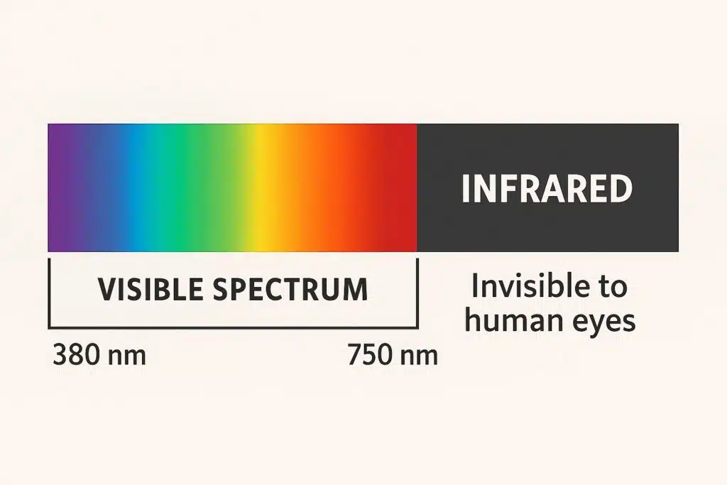
Normal LEDs emit light in the visible spectrum (roughly 380–750 nm), making colors like red, green, blue, and white. The human eye is sensitive to about 380–750 nm. In contrast, IR LEDs emit light with wavelengths typically above 700 nm. For example, near-infrared LEDs commonly emit around 800–940 nm – wavelengths our eyes cannot see. This means an IR LED might be on and bright to a camera sensor, but to us it appears dark. The figure below illustrates the visible band versus the infrared band.
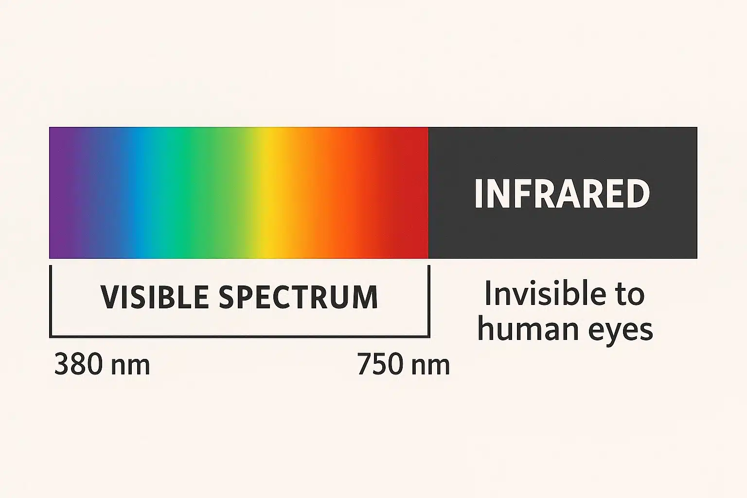
Visible light vs infrared: Visible LEDs produce photons we perceive as colors, whereas IR LEDs produce photons in the invisible infrared range. In practice, manufacturers classify IR LEDs into sub-bands (near-IR ~700–1000 nm, short-wave IR, etc.), but the key is that IR LEDs lie just beyond the visible range. For context, Wikipedia notes that the human eye responds to about 380–750 nm, so IR LEDs emit beyond that range.
Materials & Construction (GaP/GaN vs GaAs and Packaging)
LED chip materials: The color (or wavelength) of an LED depends on its semiconductor bandgap. Normal visible LEDs often use materials like gallium arsenide phosphide (GaAsP), gallium phosphide (GaP), or gallium nitride (GaN) to cover red, green, blue and white light. For example, red and green LEDs commonly use GaAsP or GaP alloys, and modern blue LEDs use GaN. In contrast, infrared LEDs typically use gallium arsenide (GaAs) or related alloys (like aluminum-gallium-arsenide, AlGaAs) tuned for IR output.
Packaging differences: Physically, IR LEDs often look similar to visible LEDs (they may have a clear or tinted epoxy lens), but there are differences. High-power IR LEDs sometimes use a dark lens or black epoxy to filter out any stray visible light, resulting in a “black” LED that hides the die. In single LEDs (like 5mm IR diodes) the epoxy might be deep red or opaque. By contrast, normal LEDs often have colored bodies or clear domes shaped for lighting. Package form factors (DIP vs SMD vs COB) exist for both types, but IR LEDs for illumination or sensing often come in arrays and specially coated packages to focus infrared output.
Electrical Characteristics
One clear difference is forward voltage. Because infrared photons have lower energy, IR LEDs require a smaller bandgap, so they conduct at lower voltages. For example, Tech-LED notes that IR LEDs have a forward voltage around 1.2–1.5 V, whereas many visible LEDs need ~2–3 V to conduct. In fact, an electronics reference states IR LEDs typically turn on at ~1.5–1.7 V, while a blue LED might need ~3.3 V.
- Forward voltage: Visible LEDs (red/green) ~2.0 V, blue ~3.3 V; IR LEDs ~1.2–1.7 V.
- Current: Both types may run similar currents (e.g. 20 mA for indicator LEDs, hundreds of mA for high-power LEDs), but IR LED datasheets often specify radiant intensity instead of luminous intensity.
- Output units: Visible LEDs are rated in lumens or candela (light output to human eye), whereas IR LEDs are rated in milliwatts (optical power) or radiant intensity (mW/sr) since output is invisible.
Applications (Lighting/Indicators vs Sensing/Communication)
Visible LEDs and IR LEDs serve very different applications. Normal LEDs are used where human-visible illumination or indication is needed: indicator lights, digital displays, color lighting, architectural and general illumination, backlights, etc. Wikipedia explains that LEDs are “widely used in indicator and display functions” and white LEDs are replacing other light sources for general lighting. On the other hand, IR LEDs are used for non-visual signaling and sensing:
- Remote controls & data transfer: TV or AC remotes use ~940 nm IR LEDs to send commands to devices. IR LEDs also enabled wireless IrDA data links and are used in some short-range wireless modules [oai_citation:13‡moon-leds.com.
- Security/night vision: IR LED illuminators flood a scene with invisible light for cameras. An IR camera in a security system or wildlife cam can see in total darkness by using IR LEDs (850/940 nm) that are imperceptible to people [oai_citation:14‡tech-led.com](https://tech-led.com/near-infrared-nir-led/#:~:text=,21). This provides covert illumination.
- Sensors and proximity: Many sensors use IR LEDs. For example, proximity sensors on phones, obstacle detectors, and automatic faucets emit IR light and detect reflections. Automatic garage door and break-beam alarms also use IR emitters and detectors.
- Medical/biometric: IR LEDs penetrate skin and are used in pulse oximeters (measuring blood oxygen), pulse sensors, and vein finders. They’re also used in various non-contact medical instruments and IR-based biometric devices (like some facial recognition systems using 850 nm flood illumination).
- Machine vision and optical comm: In industry, IR LEDs illuminate products for machine vision (sometimes using 880 nm or 940 nm to see through certain materials). In fiber optics, certain wavelengths around 850–1550 nm are used to transmit data (IR LEDs in multimode fiber).
In summary, normal LEDs provide visible light for human use (lighting, signage, indicators), whereas IR LEDs provide invisible light for devices and sensors. In fact, Tech-LED’s near-infrared LED guide emphasizes this point: a normal LED “lights up” for people, while an IR LED is used for communication or illumination that only electronic sensors detect.
Detection by Humans vs Devices
The most obvious difference is how each is perceived. You can look at a normal LED and see its light and color. By contrast, when an IR LED is on, your eyes see nothing – it looks off. This is because IR light is invisible to our eyes. To detect an IR LED, you need a camera or an IR photodiode. For example, a smartphone camera will often show a faint glow if you point it at an active remote-control LED. Tech-LED notes: “you cannot tell if an IR LED is on just by looking (since it doesn’t visibly glow), whereas a normal LED obviously lights up when active”. In practice, engineers use IR-sensitive cameras, IR viewers, or photodiodes to see IR illumination.
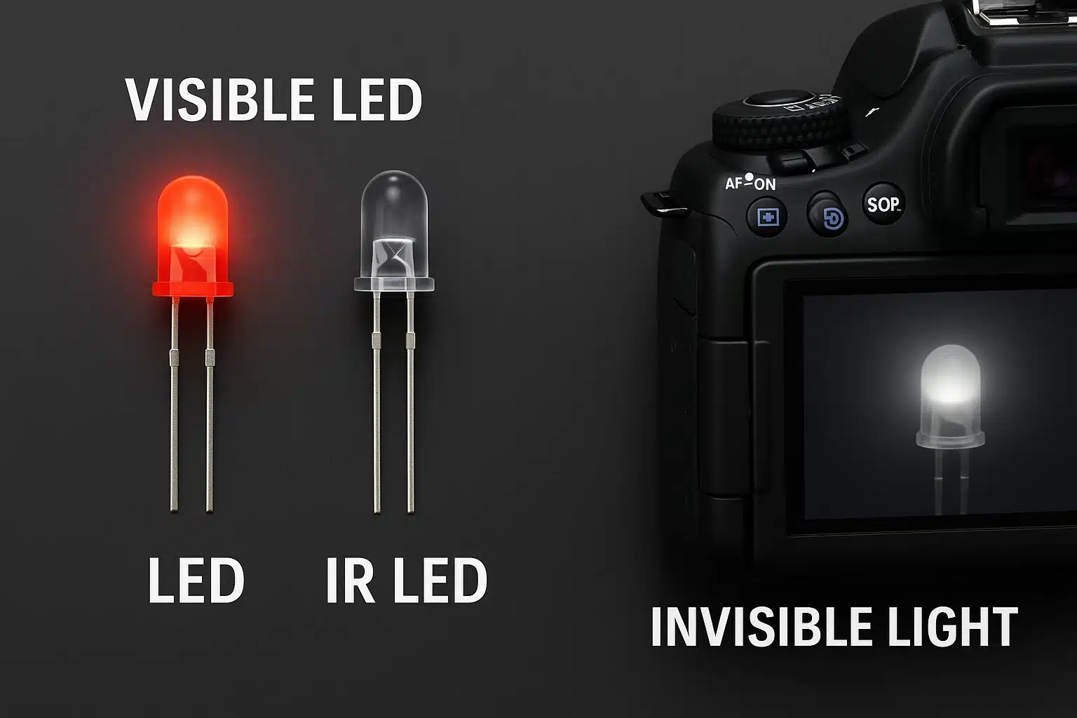
Perception: In visible LEDs, the output is designed for human perception (color and brightness). In IR LEDs, the output is for machines – a camera sensor or detector picks up the IR. This is why IR LEDs are popular in night-vision cameras and remote controls: they are “invisible” to intruders or users, but clear to electronic sensors.
Sourcing an IR LED vs a Normal LED: What Changes for an OEM
Everything above is device physics. This section is about the purchase order. Most of the friction an OEM hits moving from a visible indicator LED to an infrared emitter comes from a handful of datasheet and qualification differences, not from the optics.
The units on the datasheet are not the same units
A visible LED is a photometric part. It is binned and sold on luminous intensity in millicandela, luminous flux in lumens, and a chromaticity point (CIE x, y) or dominant wavelength. Those units are weighted by the human eye response curve, which is what you want for an indicator or a display backlight and precisely what you do not want for a sensor.
An infrared emitter is a radiometric part. It is specified on peak wavelength in nanometers, spectral bandwidth at half maximum (FWHM), total radiant flux in milliwatts, and radiant intensity in milliwatts per steradian, always at a stated drive current. Tech-LED's SMT850-25, an 850 nm top-emitting surface-mount part with an integrated lens, is published at roughly 16 to 22 mW at 50 mA and about 44 mW at 100 mA pulse drive, near 80 mW/sr. Those are the numbers you compare across candidate parts. A millicandela figure on an IR datasheet is meaningless, because the eye response curve is already negligible at 850 nm and effectively zero at 940 nm.
The practical consequence is concrete: a purchasing team that filters a distributor catalog on "brightness" returns nothing usable for an infrared BOM line. The filter has to be wavelength plus radiant intensity at a drive current the design actually uses.
Wavelength is a tolerance band, not a number
"940 nm" on a line item is a nominal peak. The real part carries a peak wavelength tolerance and an FWHM, typically tens of nanometers wide for a GaAs or AlGaAs emitter, and the peak shifts upward as the junction heats, on the order of a few tenths of a nanometer per degree C. Take that coefficient from the datasheet rather than assuming it.
Whether the drift matters is a system question, and it is the question to settle before you request quotes:
- If the receiver is a bare silicon photodiode, or a CMOS imager with the IR-cut filter removed, its response is broad (roughly 400 to 1100 nm, peaking near 900 to 980 nm) and a 20 nm shift is invisible to it.
- If the receiver sits behind a narrow bandpass filter, which is how you reject sunlight and room lighting in an outdoor or high-ambient design, drift eats your optical margin directly. Peak wavelength tolerance is then a purchase specification, and the question for the supplier is whether they can bin to it.
Visible LEDs have the same issue in a different form (dominant versus peak wavelength, plus color binning), but for them it usually resolves into an appearance argument rather than a signal-to-noise argument.
The detector belongs in the same sourcing decision
An IR emitter is never bought alone. It is bought against a detector, and the detector sets the wavelength envelope. Silicon photodiodes and phototransistors are inexpensive and respond out to about 1100 nm, which is why 780, 850, and 940 nm dominate remote control, proximity, gesture, night vision, and biometric designs. Past roughly 1100 nm silicon stops responding and the receive side has to become InGaAs, a different and considerably more expensive supply chain. That boundary, more than emitter physics, is usually what fixes an OEM's wavelength choice: staying at 850 or 940 nm keeps the detector on commodity silicon. Tech-LED's IR and NIR LED product category covers the emitter side of that range.
Continuous drive versus pulsed drive
Visible indicator LEDs are generally specified and used at a DC forward current. Many infrared emitters are not. Remote control, time-of-flight, gesture, and structured-light designs pulse the emitter hard at low duty cycle to buy range without blowing the thermal budget, so the governing number is the pulsed forward current with its stated pulse width and duty cycle, not the DC rating. The SMT850-25 figures show the gap plainly: roughly 16 to 22 mW at 50 mA DC against about 44 mW under 100 mA pulse drive.
Two consequences for sourcing. Compare candidate parts at the same drive condition or the comparison is noise. And if a datasheet publishes only a DC rating while your design is pulsed, ask for the pulsed characteristics before you commit; a supplier who cannot produce them is telling you something about their test capability.
Thermal specs earn their place on an IR BOM
Package families are shared. Both device types are available in surface-mount (SMT and SMB), through-hole, and COB. What differs is how much the thermal number matters. An indicator LED at 20 mA is thermally uninteresting. An IR illuminator drawing hundreds of milliamps, or a multi-die array such as the 60-chip L850-66-60 metal-can part, is a thermal design problem: radiant output falls as the junction heats and the peak wavelength moves at the same time. Thermal resistance from junction to solder point, in degrees C per watt, belongs on an IR selection matrix and rarely belongs on a visible indicator one.
You cannot inspect an IR part by eye
This is the quiet one. An incoming-inspection technician confirms a visible LED reel in seconds by powering one up. Nobody confirms an 850 nm reel that way, and at 940 nm there is not even a faint red glow to work from. Real verification takes a calibrated radiometer or a spectrometer, with an IR-sensitive camera good only for a crude present or absent check. Most OEMs therefore lean on the supplier's test and binning documentation, which raises the weight of two qualification questions: what is actually measured on the production line, and will the data be supplied per lot? General vendor evaluation criteria are covered in our OEM LED supplier guide. The point specific to infrared is that IR removes the cheap sanity check visible parts give you for free, so documentation substitutes for eyesight.
Request photobiological safety documentation in the same package. Bright visible light triggers a blink and aversion response; infrared does not, so a high-power IR emitter can deliver a retinal dose with no natural warning. IEC 62471 assessment is a routine part of the document set for an IR illuminator and an afterthought for an indicator LED.
IR emitter vs visible LED: the sourcing sheet side by side
| Sourcing item | Normal (visible) LED | IR LED emitter |
|---|---|---|
| Primary output spec | Luminous intensity (mcd), luminous flux (lm) | Radiant intensity (mW/sr), radiant flux (mW) |
| Color or wavelength spec | Dominant wavelength, CIE (x, y) chromaticity bin | Peak wavelength (nm) plus tolerance and FWHM |
| Typical forward voltage | ~2.0 V red and green, ~3.3 V blue (GaAsP, GaP, GaN) | ~1.2 to 1.7 V (GaAs, AlGaAs) |
| Governing drive condition | DC forward current | Often pulsed forward current with pulse width and duty cycle |
| Paired receiver | The human eye | Si photodiode or phototransistor to ~1100 nm; InGaAs beyond |
| Incoming inspection | Visual, by eye | Radiometer, spectrometer, or IR camera; supplier lot data |
| Weight of thermal spec | Low for indicators | High: radiant output and peak wavelength both drift with junction temperature |
| Safety documentation | Glare and photometric limits | IEC 62471 routinely, since IR triggers no aversion response |
| Common packages | SMT, SMB, through-hole, COB | Same families, plus multi-die arrays and metal-can assemblies |
What to put on the RFQ
For an infrared line item, a quote request that avoids a second round asks for: peak wavelength and its tolerance, FWHM, radiant intensity and radiant flux at a named drive current, pulsed forward current with pulse width and duty cycle, viewing angle or half-intensity angle, forward voltage at the same current, thermal resistance junction to solder point, package and footprint, and the lot-level test documentation you expect at incoming inspection. Marubeni part numbers encode package family, wavelength, chip count, and chip dimension directly, so a decoded part number answers several of those before a datasheet is opened.
FAQ
Q: Can I see infrared LED light without a camera?
A: No. Infrared light is beyond the human visible range. An IR LED glowing will appear dark to your eyes, although some IR LEDs (especially 850 nm) may emit a faint red glow in the visible band. To verify an IR LED is on, use an IR-sensitive camera or an IR photodiode.
Q: Why do IR LEDs have a lower forward voltage than visible LEDs?
A: The forward voltage of an LED is set by its semiconductor bandgap. IR LEDs use materials with smaller bandgaps (e.g. GaAs), so they conduct and emit at ~1.2–1.7 V. Visible LEDs (green, blue, UV) have larger bandgaps (GaN, etc.) requiring 2–3+ V.
Q: What materials are used in IR LEDs vs normal LEDs?
A: Normal visible LEDs typically use materials like GaAsP/GaP for reds/greens and GaN for blues. In contrast, IR LEDs use GaAs or AlGaAs-based chips specifically engineered for IR emission. These different materials tune the emitted wavelength.
Q: How do I distinguish an IR LED from a regular LED?
A: IR LEDs often look similar to regular LEDs but may have a black, deep red, or opaque lens. You won’t see it glow when on. To test one, point a digital camera at the LED while powering it; the camera will usually show a purplish light if it’s an IR LED.
Q: What are common uses for IR LEDs that normal LEDs can’t do?
A: IR LEDs are used in applications where human vision isn’t needed or would be intrusive – remote controls, surveillance cameras, IR communication links, proximity sensors, medical sensing, etc. They allow devices to “see” or communicate without visible light.
Q: What is the difference between sourcing an IR LED and a normal LED?
A: The spec sheet changes units. A normal LED is bought on photometric numbers (millicandela, lumens, a chromaticity bin) because a human is the receiver. An IR LED is bought on radiometric numbers (peak wavelength and its tolerance, FWHM, radiant intensity in mW/sr, radiant flux in mW) at a named drive current, because a photodiode is the receiver. Add the pulsed forward current rating if the design pulses the emitter, and the thermal resistance if it runs above indicator-level current.
Q: How do I compare IR LED datasheets from different suppliers?
A: Normalize the drive condition first. Radiant intensity quoted at 20 mA, 50 mA, and 100 mA pulse are not comparable numbers, and one supplier quoting pulsed output against another quoting DC output will look twice as good while being the same part class. Fix a current, a pulse width, and a duty cycle that match your design, then compare radiant intensity, peak wavelength tolerance, FWHM, viewing angle, and forward voltage at that condition.
Q: How do I verify an incoming IR LED shipment is the right wavelength?
A: Not by eye. At 850 nm you may see a faint red glow and at 940 nm you will see nothing, and neither observation tells you the peak wavelength. A spectrometer gives the peak and FWHM directly, a calibrated radiometer or photodiode with a known responsivity curve gives you output at a drive current, and an IR-sensitive camera only tells you the part is emitting. In practice most OEMs specify lot-level test data from the supplier and spot-check against it.
Q: Can an OEM use the same package and footprint for an IR LED and a normal LED?
A: Often yes, since surface-mount (SMT and SMB), through-hole, and COB families exist for both. What does not carry over is the thermal and drive envelope. IR emitters used for illumination or sensing frequently run at far higher current than an indicator LED in the same footprint, so the board needs the copper and the thermal path to match the IR part's junction-to-solder-point resistance, not the visible part's.
What is the difference between an IR sensor and an IR LED?
An IR sensor detects infrared radiation while an IR LED (light-emitting diode) emits infrared light. The IR sensor is designed to respond to infrared light signals, which are invisible to the human eye, whereas the IR LED serves as a source, producing light within the infrared spectrum, typically around 850nm IR.
How do IR receivers work with IR LEDs?
IR receivers are devices that detect and interpret signals emitted by IR LEDs. When an IR LED emits infrared light, the IR receiver can capture this light if it falls within its sensitivity range, allowing it to process the information, such as in remote controls or various applications of IR technology.
What are the applications of IR sensors and IR LEDs?
IR sensors and IR LEDs have numerous applications, including remote controls, motion detectors, and data transmission. They are commonly used in security systems, TVs, and other consumer electronics, as well as in industrial settings for various sensing applications.
What is the difference between different types of IR LEDs?
The differences between types of IR LEDs generally relate to their wavelength, power output, and design. For instance, high power LEDs emit stronger infrared light, while standard IR LEDs may be used for basic remote control functions. Each type serves specific needs based on the application, such as whether the light is for short-range or long-range detection.
How does an IR transmitter LED differ from a standard LED?
An IR transmitter LED is specifically designed to emit infrared light, which is not visible to the human eye, while a standard LED emits visible light. The IR transmitter LED is optimized to generate light at specific wavelengths suitable for applications like remote signaling, whereas standard LEDs are used for general illumination.
Can IR sensors detect ambient light?
Most IR sensors are designed to detect infrared light rather than visible ambient light. However, some advanced models can differentiate between IR signals and ambient light, allowing them to function accurately in varying lighting conditions. This capability is crucial in applications where infrared signals might be affected by external light sources.
What is the difference in light emission between IR LEDs and visible light LEDs?
The primary difference in light emission is that IR LEDs emit infrared light, which is not visible to the human eye, while visible light LEDs emit light that can be seen. The light emitted by IR LEDs often serves purposes such as communication or detection, whereas visible light LEDs are used for general lighting and display purposes.
How are IR LEDs used in remote controls?
An IR LED is the transmitter inside almost every remote control. When you press a button, the remote's IR LED, usually a 940 nm infrared LED, pulses on and off thousands of times per second to encode the command, and an infrared receiver in the TV, air conditioner, or set-top box decodes those pulses. 940 nm is chosen because it is completely invisible to the human eye yet sits near the peak sensitivity of low-cost silicon photodiodes. So an IR LED for remote control is simply a standard infrared emitter driven with a modulated signal rather than a steady current.
Are there IR LED light bulbs and illuminators?
Yes. Whereas a normal LED light bulb emits visible light, IR LED light bulbs and IR illuminators emit invisible infrared (typically 850 nm or 940 nm) to flood a scene with light only cameras can see. They screw into standard sockets or mount alongside security cameras to provide covert night-vision lighting. Note that these IR LED lights are illuminators for cameras and sensors, not human-visible lighting, to your eyes they look off, or show only a faint red glow from an 850 nm array.
What is an infrared receiver LED?
Strictly speaking, the emitter is the IR LED and its counterpart is the infrared receiver, a photodiode or phototransistor tuned to the emitter's wavelength. The two are sold as a matched emitter/detector pair: the IR LED transmits, and the infrared receiver detects the light (or its reflection) and converts it to an electrical signal. This emitter-plus-receiver pairing is the basis of remote controls, proximity sensors, break-beam detectors, and optical encoders.
Ready to explore LEDs for your project? Contact the Tech-LED team for expert advice and custom solutions. Contact Tech-LED.