Tech-led.com


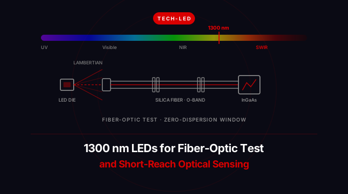
Summary: A 1300 nm LED is a short-wave infrared emitter that lands in the O-band of standard silica fiber, the window where chromatic dispersion in single-mode fiber crosses zero and where multimode insertion-loss testing is specified. That makes it a working component for fiber test sets, short-reach optical links, and fiber-coupled sensing rather than a general-purpose illuminator. This guide covers why 1300 nm is a fiber wavelength first, how an incoherent Lambertian LED couples into 50/125 and 9/125 fiber and how much power you lose doing it, why InGaAs detection still works well at this band, what to specify (center wavelength, bin, FWHM, radiant power, rise and fall time, package and thermal path), and how 1300 nm compares with 1050, 1200, 1450, and 1550 nm sources.
For the broader SWIR context, how 1300 nm sits inside the 1050 to 1750 nm band and how wavelength selection works across the whole range, see our SWIR LED Lighting Guide.
Why 1300 nm is a fiber wavelength before it is a sensing wavelength
Most SWIR wavelengths in this catalog are chosen because of what they do to a material. 1450 nm is picked for the water absorption peak, 1650 nm for the C-H bond overtone. 1300 nm is different. It is chosen because of what silica glass does to it.
Standard single-mode fiber (ITU-T G.652) has two properties that meet near 1310 nm. Attenuation has already fallen away from the high-scattering visible and near-infrared region, and material dispersion cancels waveguide dispersion, so total chromatic dispersion passes through zero. A pulse launched at the zero-dispersion wavelength spreads far less per kilometer than the same pulse at 1550 nm, which is why the O-band (1260 to 1360 nm) became the standard band for short and medium-reach links where dispersion, not loss, is the limit.
| Fiber window | Nominal wavelength | Typical G.652 attenuation | Chromatic dispersion | What it is used for |
|---|---|---|---|---|
| First | 850 nm | 2 to 3 dB/km | High | Short-reach multimode links, VCSEL transceivers |
| Second (O-band) | 1310 nm | 0.32 to 0.40 dB/km | Near zero | Short and medium reach, multimode loss testing |
| Water peak | 1383 nm | Elevated on legacy fiber | n/a | Avoided; suppressed on low-water-peak G.652.D |
| Third (C-band) | 1550 nm | 0.18 to 0.22 dB/km | Roughly 17 ps/nm/km | Long haul, amplified links, eye-safe sensing |
The practical consequence for an LED is favorable. An LED is a broad emitter, typically tens of nanometers wide, so chromatic dispersion multiplies its spectral width by the fiber's dispersion coefficient to give pulse spreading. At 1550 nm that product is punishing for a broad source. Near the zero-dispersion wavelength it nearly vanishes, so a wide-spectrum incoherent source stays usable over hundreds of meters of fiber. That is the entire historical reason LEDs, not lasers, drove the first generation of 1300 nm fiber links, and it is still why a broadband source is tolerable at this band and awkward at others.
What a 1300 nm LED actually is
A 1300 nm emitter is built on indium phosphide, with an InGaAsP or InGaAs active region lattice-matched to the InP substrate. That is the same material system used for the neighboring 1200 nm SWIR emitters, and it is a different world from the GaAs and AlGaInP devices that cover the near-infrared and visible catalog.
Three properties follow from that construction and they set the boundaries of every design at this wavelength.
- It is incoherent and spectrally broad. Spontaneous emission linewidth scales roughly with the square of the wavelength, so a 1300 nm LED is several times wider in nanometers than a visible LED at the same junction temperature. Confirm the FWHM on the specific datasheet rather than assuming a number.
- It is Lambertian, not directional. The die radiates into a wide angle. There is no beam to speak of, only an emitting area and a radiation pattern.
- It is low in radiant power per unit area compared with a laser diode. InP-based emitters have lower wall-plug efficiency than GaAs near-infrared devices, which is a large part of why cost per milliwatt across the SWIR band runs roughly 10 to 100 times that of a visible LED.
None of those are defects. Low coherence removes speckle and modal noise. A wide radiation pattern is what you want when you are flooding a target or overfilling a multimode core. Low peak power is what keeps the source in a benign optical safety category. They only become problems when a design asks a 1300 nm LED to behave like a 1310 nm DFB laser.
Fiber-optic test: where a 1300 nm LED is the correct source
Optical loss test sets pair a stable source with a power meter and measure insertion loss on an installed link. The relevant standards fix the wavelengths. Multimode insertion-loss testing (IEC 61280-4-1, TIA-526-14) is specified at 850 nm and 1300 nm. Single-mode testing (IEC 61280-4-2, TIA-526-7) is specified at 1310 nm and 1550 nm. Any test source built for structured cabling therefore needs a 1300 nm channel, and for the multimode side an LED is a natural fit.
The reason is launch condition. Insertion loss on multimode fiber depends heavily on how the modes are excited. A narrow, low-NA laser launch underfills the core and reports optimistic loss. A wide-angle source overfills it and reports pessimistic loss. Modern practice constrains the launch with encircled-flux limits so results are reproducible between instruments, and that conditioning is applied regardless of source type. What an LED contributes is a stable, mode-rich, low-coherence starting point that does not introduce modal noise or speckle-driven measurement scatter.
A few boundaries worth stating plainly:
- OTDRs are laser instruments. Single-ended backscatter measurement needs high peak power in short pulses and a narrow spectrum. An LED cannot do that job.
- Single-mode insertion loss is a laser measurement in practice. The coupling penalty into a 9 µm core (covered below) leaves too little power for long links, though an LED can still serve short single-mode jumper and connector checks.
- Continuity, polarity, and connector-endface work is where a broad source shines. Wavelength-selective test heads, multimode link certification, and reference-grade loss sets at 1300 nm are the mainstream LED applications.
Coupling a 1300 nm LED into fiber
This is the number that decides whether a design works, and it is the one most often skipped. Coupled power from a Lambertian emitter into a step-index fiber scales with the core area and with the square of the fiber's numerical aperture, when the emitting die is larger than the core. Étendue is conserved. You cannot lens your way past it.
| Fiber type | Core diameter | Typical NA | Relative capture from a Lambertian die | Practical use with a 1300 nm LED |
|---|---|---|---|---|
| OM1 multimode | 62.5 µm | 0.275 | Highest of the silica options | Legacy multimode test, short-reach sensing |
| OM2 to OM4 multimode | 50 µm | 0.200 | Roughly a third of OM1 | Standard multimode loss testing |
| G.652 single-mode | 9 µm (mode field ~9.2 µm) | 0.14 | Orders of magnitude lower | Short jumpers only; expect heavy loss |
| Large-core plastic (POF) | 200 to 1000 µm | 0.30 to 0.50 | Very high | Short industrial sensing runs, but POF attenuation at SWIR is severe |
Two design rules fall out of the table. First, if the system needs single-mode fiber and any real link budget, the source is a laser, not an LED. The mismatch between a die tens of microns across radiating into a hemisphere and a 9 µm core accepting a 0.14 NA cone is not a coupling-optics problem, it is a brightness problem. Second, plastic optical fiber is a trap at 1300 nm. Its large core looks attractive for capture, but PMMA attenuation in the SWIR is orders of magnitude worse than silica, so any capture advantage is spent within the first meter.
For a fiber-coupled build, the choices that actually move the number are die size relative to core, emitter-to-fiber standoff, and whether the package presents a flat window or an integrated lens. A ball-lensed or pigtailed package buys real improvement over a bare surface-mount part butted against a ferrule, but it buys a factor, not an order of magnitude.
Short-reach optical sensing at 1300 nm
Away from fiber, 1300 nm earns its place through a spectral coincidence: it sits in a relative valley of the water absorption spectrum, between the overtone band near 1190 nm and the strong band at 1450 nm. Light at 1300 nm travels through wet and aqueous media with less loss than the wavelengths on either side.
| Sensing task | Why 1300 nm | What to watch |
|---|---|---|
| Transmission through moist or aqueous media | Local minimum in water absorption between the 1190 and 1450 nm bands | Poor choice if you want to measure moisture; use 1450 nm for that |
| Deep-tissue and vital sensing | Falls in the second biological window (roughly 1100 to 1350 nm), where scattering and absorption in tissue are both low | Optical safety review still required; this band is below the 1400 nm eye-safety threshold |
| Through-plastic and through-package inspection | Many polymers and fillers transmit in the SWIR where they are opaque in the visible | Confirm the specific resin; absorption features vary by polymer |
| Short-reach optical links and reflective sensing | Zero-dispersion window; broad source is tolerable | Link budget is set by coupling, not fiber loss, at these distances |
| Fiber-coupled reflective and level sensing | Low-coherence source removes speckle and modal noise from the return signal | Return path optics dominate; specify the detector with the source |
The tissue point deserves care. Marubeni's SWIR flip-chip die family is positioned for exactly this, and the second biological window at 1100 to 1350 nm is the reason: penetration depth into tissue is longer there than in the visible or conventional near-infrared, so light reaches deeper structures non-invasively. That is a genuine application driver at 1300 nm. It is also a reminder that 1300 nm does not carry the inherent eye-safety margin that 1450 nm and above enjoy. Wavelengths below roughly 1400 nm still reach the retina, so a 1300 nm system needs the same IEC 60825-1 classification work that a 1050 or 1200 nm system needs.
Detector selection
Silicon is out. Its response collapses past about 1000 nm and it is effectively blind beyond 1100 nm, so nothing in a standard CMOS or CCD imaging chain will see a 1300 nm source.
- InGaAs photodiodes and cameras are the default. Standard InGaAs covers roughly 900 to 1700 nm, and 1300 nm sits comfortably inside that range at something like 0.8 to 0.9 A/W against a peak near 1.0 A/W at 1550 to 1600 nm. You keep most of the detector's sensitivity, which is a real advantage over 1750 nm work at the far edge of the response curve.
- Germanium photodiodes respond from roughly 800 to 1600 nm and are sometimes cheaper, at the cost of substantially higher dark current and worse temperature stability. They remain common in older optical power meters.
- Optical power meters in fiber test sets are usually InGaAs and are calibrated at the standard wavelengths, 1300 and 1310 nm among them. Set the meter to the correct wavelength before referencing, because the calibration factor differs between them even though the wavelengths are close.
That last point is a recurring field error. A 1300 nm LED source and a meter left set to 1310 nm will not agree, and the discrepancy looks like link loss.
Specifying a 1300 nm LED
Wavelength is the first decision. These are the seven parameters that follow it, and they are what turn an application into a buildable part number.
| Parameter | Why it matters at 1300 nm | How to specify |
|---|---|---|
| Center wavelength and bin | Detector calibration and fiber-window alignment both depend on it | State the target center and the acceptable tolerance; tighter bins are sorted parts at higher cost |
| Spectral width (FWHM) | Sets dispersion penalty in fiber and cross-talk in multi-band sensing | Take the number from the datasheet; do not scale from a visible-LED figure |
| Radiant power or radiant intensity | The real budget input, before coupling loss | Radiant power in mW at a stated forward current, plus radiant intensity in mW/sr if you are flooding a target |
| Radiation pattern and emitting area | Directly sets fiber coupling efficiency | Ask for half-angle and die dimensions, not just a viewing-angle number |
| Rise and fall time | Decides whether the part can be modulated for lock-in detection or link work | Specify at the modulation frequency you intend to use |
| Package and thermal path | Junction temperature moves the peak wavelength and reduces output | Choose SMD, high-power, or bare die on submount based on the thermal budget and the optical geometry |
| Forward voltage and drive scheme | InP emitters run at lower Vf than visible LEDs; drivers sized for visible parts misbehave | Design the constant-current driver around the actual Vf across the temperature range |
Two of those interact in a way worth calling out. Junction temperature shifts the peak wavelength of an InP-based emitter toward longer wavelengths, and the shift per kelvin is larger than engineers coming from visible LEDs expect. If the design is doing wavelength-sensitive work, either stabilize the junction temperature or budget for the drift. The datasheet coefficient is the design number.
On packaging, the current direction in this portfolio is toward smaller. Marubeni's epitex F Series introduced a flip-chip InP structure that removes the bonding wires, which cuts mounting height, eliminates the wire shadow on the emitting surface, and allows dense multi-die arrays. The 1300 nm member of that family is the C1300F-2717-X die. For fiber coupling and for compact sensing heads, the absence of a wire shadow simplifies the optical design considerably.
How 1300 nm compares with neighboring SWIR bands
| Wavelength | Chosen for | Detector fit | Eye-safety margin above 1400 nm |
|---|---|---|---|
| 1050 nm | Short-range SWIR imaging, silicon wafer inspection | Just past the silicon cutoff; strong on InGaAs | No |
| 1200 nm | The IR to SWIR crossover; semiconductor inspection | InGaAs and extended InGaAs both respond | No |
| 1300 nm | Fiber O-band, zero dispersion, short-reach sensing, second biological window | InGaAs at roughly 0.8 to 0.9 A/W | No |
| 1450 nm | Moisture and food inspection | InGaAs, near peak | Yes |
| 1550 nm | Eye-safe industrial sensing, telecom C-band | InGaAs at peak responsivity | Yes |
| 1650 nm | Oil and plastic sorting, hydrocarbon detection | InGaAs, response falling | Yes |
Read across that table and the split is clear. Below 1400 nm the wavelengths are selected for what they let you see through, and safety classification is on you. Above 1400 nm they are selected for what they absorb, and the eye-safety margin comes free. 1300 nm is the last band in the lower group and the only one aligned to a fiber standard, which is why its application set looks so different from its neighbors.
FAQ
What is a 1300nm LED used for?
Fiber-optic test equipment and short-reach optical sensing. It is the specified multimode insertion-loss test wavelength alongside 850 nm, it sits in the O-band where single-mode fiber dispersion crosses zero, and away from fiber it is used for transmission through moist media, deep-tissue and vital sensing in the second biological window, and through-plastic inspection. It is not a general illumination part.
Can I use a 1300nm LED for fiber optic testing?
Yes, for multimode insertion-loss testing it is a good fit, and 1300 nm is one of the two reference wavelengths that IEC 61280-4-1 and TIA-526-14 specify for multimode links. The low-coherence, mode-rich launch avoids the modal noise a laser source can introduce. It is a poor choice for OTDR work, which needs a high peak-power narrow-spectrum laser, and for long single-mode links, where the coupling penalty into a 9 µm core leaves too little power.
What is the difference between a 1300 nm LED and a 1310 nm laser diode?
Spectral width, coherence, brightness, and coupling. The LED emits spontaneously over a wide band into a wide angle, so it couples well into a 50 or 62.5 µm multimode core and very poorly into single-mode. The laser emits a narrow line into a narrow angle and couples efficiently into single-mode fiber. Choose the LED when you want a stable broad source with no speckle and a benign safety profile. Choose the laser when you need a link budget, reach, or high modulation rates.
Do I need an InGaAs detector for a 1300nm LED?
Yes. Silicon photodiodes and standard CMOS or CCD sensors are effectively blind past about 1100 nm, so they will not see a 1300 nm source at all. Standard InGaAs covers roughly 900 to 1700 nm and holds around 0.8 to 0.9 A/W at 1300 nm. Germanium photodiodes also respond in this band but carry higher dark current and worse temperature stability.
Is a 1300 nm LED eye-safe?
Not inherently. The eye-safety margin engineers associate with SWIR comes from water absorption in the cornea and aqueous humor at wavelengths above roughly 1400 nm, which keeps light off the retina. 1300 nm is below that threshold, so retinal exposure is still possible and the system needs proper IEC 60825-1 classification. Treat it the same way you would treat a 1050 or 1200 nm design, not the way you treat 1550 nm.
How much power can I actually couple into fiber from a 1300nm LED?
It depends almost entirely on the fiber, not on the LED. Coupled power from a Lambertian die scales with core area and with the square of the numerical aperture. A 62.5 µm OM1 core captures the most of the silica options, a 50 µm core roughly a third of that, and a 9 µm single-mode core orders of magnitude less. A lensed or pigtailed package improves the result by a useful factor but cannot overcome the underlying brightness mismatch.
Where 1300 nm fits in the SWIR portfolio
1300 nm belongs to the lower half of the SWIR band, where wavelength selection is driven by transmission rather than absorption, and it is the one band in that group tied to a fiber standard. If your problem statement contains the words insertion loss, O-band, multimode certification, fiber-coupled sensing head, or second biological window, this is the wavelength to evaluate first. If it contains moisture content, polymer identification, or outdoor eye-safe sensing, the right answer is further up the band.
For available packages, datasheets, and sample requests across 1050 to 1750 nm, see the SWIR LED product category. For the full seven-step component selection sequence and the band-by-band tradeoffs, the SWIR LED Lighting Guide is the pillar reference.