Tech-led.com


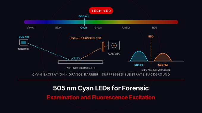
Summary: A 505 nm cyan LED is an InGaN emitter sitting between blue and green, and it earns its place in a forensic light source and a fluorescence instrument for the same reason: it excites a target while leaving the background alone. Optical brighteners in paper, fabric, and detergent residue absorb in the UV-A and violet and stop responding by about 440 nm, so a cyan excitation band suppresses the substrate glow that swamps a 415 or 450 nm examination. Paired with an orange long-pass barrier filter near 550 nm, 505 nm is the working band for indanedione-zinc and DFO treated latent prints, rhodamine dye stains, and fluorophores in the 495 to 515 nm absorption range. This guide covers band-and-filter pairing, why cyan costs you radiant flux (the green gap), the dominant-versus-peak wavelength trap in visible LED binning, and what to put on a specification.
For the wider problem of matching an excitation LED to a specific dye, see our guide to choosing an LED for fluorescence microscopy.
The band-and-filter pairing that defines a forensic light source
An alternate light source (ALS) is not one lamp. It is a set of narrow excitation bands, each used with a long-pass barrier filter that blocks the excitation light and passes only the longer-wavelength fluorescence. The examiner selects the band that makes the target fluoresce and the filter that makes everything else disappear. 505 nm is one band in that set, and it is chosen for specific targets.
| Excitation band | Typical barrier filter | What it is used for | Failure mode |
|---|---|---|---|
| 365 nm (UV-A) | Clear UV-blocking | Ardrox and other UV-reactive treatments, some inks and fibers | Substrate and brightener fluorescence is at its worst here |
| 415 nm (violet) | Yellow, ~495 nm | Bruise and injury contrast (hemoglobin absorption, not fluorescence), some inks | Strong paper and fabric background |
| 445 to 455 nm (blue) | Yellow to orange, ~495 to 530 nm | Body fluid stains, basic yellow 40 treated prints, bone and trace recovery | Detergent and brightener background still significant |
| 505 nm (cyan) | Orange, ~550 nm | Indanedione-zinc and DFO treated prints, rhodamine dye stains, fibers that only respond above 490 nm | Lower excitation efficiency for body fluids than 450 nm |
| 530 nm (green) | Orange to red, ~590 nm | Rhodamine 6G at its absorption peak, ninhydrin-zinc complexes | Barrier filter starts cutting into useful emission |
| 570 nm (amber) | Red, ~610 nm and up | Dark and heavily patterned substrates, some fluorescent powders | Very little Stokes room left |
Two constraints set that whole table. First, the excitation band and the barrier filter must not overlap, or excitation light leaks straight into the eye or camera and drowns the signal. Second, the barrier filter has to sit inside the target's emission band, or you block the fluorescence along with the excitation. As the excitation band moves to longer wavelengths, the room between the two shrinks, which is why the useful ALS set runs out somewhere in the orange.
Why cyan is in the kit: substrate background, not target brightness
The instinct is to excite as hard as possible, and shorter wavelengths carry more energy per photon. That instinct is why a lot of examinations start at 365 or 415 nm and go badly.
Almost every substrate an examiner works on has been treated with fluorescent whitening agents. Stilbene-based optical brighteners in office paper, laundered fabric, and detergent residue absorb strongly in the UV-A and near-violet and re-emit in the blue, around 420 to 470 nm. Under a 365 or 415 nm source, the entire substrate glows. Under a 450 nm source, it glows less. By 505 nm, brighteners are no longer being excited at all, and the background falls away.
That is the engineering argument for cyan. It is not that 505 nm excites the target more efficiently. For most fluorophores in the ALS repertoire it excites them somewhat less efficiently than a shorter band would. It is that the contrast ratio, which is what actually determines whether a print is visible, improves because the denominator collapses. A weaker signal on a black background beats a stronger signal on a glowing one.
The same logic applies in the lab. Autofluorescence in biological samples, plastics, culture media, and mounting adhesives is strongest under UV and violet excitation and declines steadily through the visible. Moving the excitation line up to cyan is a standard way to buy signal-to-noise when the sample fights back.
What a 505 nm LED is made of, and what that costs
A 505 nm emitter is InGaN on sapphire or silicon carbide, the same material system as a 450 nm blue LED but with a higher indium fraction in the quantum wells to push the emission longer. That extra indium is where the trouble starts.
Raising the indium content increases lattice mismatch and strain in the active region. The strain generates piezoelectric polarization fields that tilt the quantum well and physically separate the electron and hole wavefunctions, the quantum-confined Stark effect, which reduces the radiative recombination rate. Higher indium content also brings more crystalline defects. The result is the well-documented green gap: external quantum efficiency for InGaN emitters falls off progressively past roughly 480 nm and is at its worst in the green, before recovering in the AlInGaP red devices further along the spectrum.
Three practical consequences follow, and every one of them shows up in a design review.
- Radiant flux per die is lower. A 505 nm die of a given size at a given drive current delivers a fraction of the radiant power of a 450 nm die under the same conditions. Budget for more emitters, more current, or more collection optics than a blue design of the same geometry would need.
- The peak wavelength walks with drive current. As current rises, injected carriers screen the polarization field and the well flattens, so the emission blue-shifts. The effect is larger for cyan and green than for blue because the fields are stronger. A few nanometres of shift between low current and rated current is normal. Read it off the datasheet's wavelength-versus-current curve rather than assuming.
- The peak wavelength barely moves with temperature. InGaN emitters drift on the order of 0.03 to 0.04 nm/K, roughly an order of magnitude less than the GaAs near-infrared devices used for sensing. Thermal wavelength stability is genuinely good here. Thermal output droop, on the other hand, is real, and cyan and green devices droop harder than blue.
The current-dependent shift is the one that catches instrument builders. If the LED sits behind a narrow excitation bandpass filter, a source that moves several nanometres between 10% and 100% drive is moving relative to a fixed passband. Optical output then stops being proportional to current, and any calibration taken at full power is wrong at low power. Either drive the emitter at a fixed current and modulate with a shutter or pulse-width control, or characterize the shift and widen the excitation filter to cover it.
Expect a spectral full width at half maximum in the region of 30 to 40 nm for a cyan InGaN device, broader than a blue emitter and broader still than anything you would call narrowband. Confirm it on the specific datasheet. For fluorescence work that width usually needs trimming with an excitation filter so the long tail does not reach into the barrier filter's passband.
Dominant wavelength, peak wavelength, and the visible-LED binning trap
This is the single most common specification error on cyan parts, and it comes from visible LEDs being sold to two different audiences.
Peak wavelength is radiometric. It is the wavelength at which the spectral power distribution is highest, and it is what determines how well the source overlaps a fluorophore's absorption band or a filter's passband.
Dominant wavelength is colorimetric. It is derived from the emitter's chromaticity coordinates by projecting from the white point through the source point to the CIE spectral locus. It describes the hue a human observer perceives, which is what matters when the LED is a status indicator, a signal light, or part of a color-mixing array.
For a broad emitter these are different numbers, and the difference is largest in the cyan and green region where the spectral locus curves most sharply. Visible LED catalogs overwhelmingly bin on dominant wavelength, because most visible LEDs are sold for color. A part sold as "505 nm cyan" may well be a dominant-wavelength bin, and its peak can sit several nanometres away.
The same split shows up in the output specification. Cyan parts are routinely rated in millicandela or lumens, which are photometric units weighted by the human eye's response. Excitation work needs radiometric units, milliwatts of radiant power or milliwatts per steradian of radiant intensity. The two are not interchangeable, and at 505 nm the conversion factor is unusually treacherous because the photopic response is climbing steeply through this region.
| Quantity at 505 nm | Value | Why it matters |
|---|---|---|
| Photopic luminous efficiency V(λ) | ~0.41 | 1 W of optical power at 505 nm reads as roughly 280 photopic lumens |
| Scotopic luminous efficiency V'(λ) | ~1.0 (the scotopic peak is 507 nm) | The same 1 W reads as roughly 1,700 scotopic lumens, a ratio of about six |
| V(λ) slope through the band | Rising steeply from 0.32 at 500 nm to 0.50 at 510 nm | A 5 nm wavelength error changes the photometric reading by more than 20% with no change in radiant power |
Read the last row carefully. Two cyan LEDs with identical radiant power but peaks 10 nm apart will differ by roughly 50% in millicandela. If you specify the part in photometric units and the vendor ships a different bin, the radiant power you actually receive is not what you thought you bought. Specify 505 nm parts radiometrically, in mW or mW/sr at a stated forward current, and specify peak wavelength alongside any dominant wavelength bin.
One more source of confusion: "505" appears constantly in microscopy catalogs as a dichroic mirror edge, not as a source. A 505 nm long-pass dichroic is a standard component in GFP and FITC filter cubes, splitting 488 nm excitation from 510 nm emission. Searching on the number alone returns filter part numbers mixed in with emitters.
Fluorescence excitation at 505 nm
Cyan is a useful excitation line for any fluorophore whose absorption band peaks between roughly 495 and 515 nm, and a usable one on the flanks either side.
| Fluorophore | Excitation peak | Emission peak | Fit at 505 nm |
|---|---|---|---|
| Fluo-3 (calcium indicator) | ~506 nm | ~526 nm | Excellent, essentially on peak |
| YFP, Venus, mCitrine | ~514 to 516 nm | ~527 to 529 nm | Good, on the rising flank |
| Alexa Fluor 514 | ~517 nm | ~542 nm | Good, on the rising flank |
| Fluo-4 (calcium indicator) | ~494 nm | ~516 nm | Good, on the falling flank |
| Calcein, SYBR Green I | ~495 to 497 nm | ~515 to 520 nm | Good, on the falling flank |
| FITC, Alexa Fluor 488, eGFP | ~488 to 495 nm | ~510 to 519 nm | Usable but off-peak; 470 to 490 nm excites harder |
| Propidium iodide | ~535 nm (broad) | ~617 nm | Usable; the absorption band is wide enough to reach |
| Rhodamine 6G | ~526 nm | ~555 nm | Usable; 530 nm excites harder but 505 nm gives more Stokes room |
| Cy3, TRITC | ~547 to 555 nm | ~565 to 572 nm | Poor; use a green or amber line |
The pattern worth internalizing is that a 505 nm LED with a 30 nm FWHM is not a laser line. Trimmed with an excitation filter, it delivers a band that covers a good part of the 495 to 515 nm window, which means one emitter can serve several dyes in that range instead of one. That is an advantage over a 488 nm laser for a multi-dye instrument, and a disadvantage anywhere the measurement needs a defined single wavelength.
Beyond forensics: where else 505 nm gets specified
| Application | Why 505 nm | What to watch |
|---|---|---|
| Clinical and analytical colorimetry | The quinoneimine chromogen produced by peroxidase-coupled (Trinder) assays for glucose, cholesterol, and triglycerides absorbs near 500 to 505 nm, so cyan is a standard photometer channel | Absorbance work needs a stable, filtered source; specify radiant power and drift, not brightness |
| Scotopic and mesopic photometry | The scotopic response peaks at 507 nm, so a cyan LED is the natural reference source for rod-response and S/P ratio measurement | Calibration-grade work needs a characterized spectrum, not a nominal bin |
| Machine vision contrast | Cyan is complementary to red and orange, so it maximizes absorption contrast on red features, print, and packaging | Silicon sensor response at 505 nm is well below its peak; check the camera QE curve |
| Subsea imaging and short-range optical links | The blue-green window is where water attenuation is lowest; the minimum sits nearer 470 to 490 nm in clear open ocean and shifts green in coastal water, so cyan is the compromise band | Attenuation is highly site-dependent; measure the water you are actually working in |
| Fluorescence-based flow and plate readers | Covers the 495 to 515 nm dye family from one emitter, without a laser | Broad FWHM must be trimmed; check overlap with the emission filter |
| Signal, marine, and aviation indication | Cyan is a distinct signal hue with high scotopic visibility | Colorimetric application; here dominant wavelength binning is the correct specification |
Note how the last row inverts the specification advice given earlier. That is not a contradiction, it is the whole point. Dominant wavelength is the right specification when a human eye is the detector, and the wrong one when a fluorophore or a photodiode is.
Specifying a 505 nm cyan LED
| Parameter | Why it matters at 505 nm | How to specify |
|---|---|---|
| Peak wavelength and bin | Sets overlap with the fluorophore absorption band and the excitation filter passband | State peak wavelength and tolerance explicitly, and do not accept a dominant-wavelength bin as a substitute |
| Spectral width (FWHM) | A 30 to 40 nm source has tails that can reach the barrier or emission filter | Take FWHM from the datasheet and check the spectrum's long tail against the filter's blocking curve, not just its cut-on |
| Radiant power or radiant intensity | The actual excitation budget; photometric ratings hide it | mW at a stated forward current for a collected beam, mW/sr for a flood; refuse mcd-only data |
| Wavelength shift with drive current | InGaN cyan blue-shifts as current rises, moving the source relative to a fixed excitation filter | Ask for the wavelength-versus-current curve; drive at fixed current and modulate optically if the shift matters |
| Wavelength shift with temperature | Low for InGaN (roughly 0.03 to 0.04 nm/K), so the spectrum is stable, but output droop is not | Design the thermal path for flux stability rather than wavelength stability |
| Thermal resistance and package | Cyan efficiency is already reduced by the green gap, so waste heat per optical watt is high | Junction-to-case thermal resistance in K/W, plus a defined board and heatsink path |
| Radiation pattern and emitting area | Decides uniformity across an examination area and how much flux an optic can collect | Half-angle and die dimensions; narrow-angle lensed parts for standoff work, wide-angle for close flood |
| Rise and fall time | Needed for lock-in or gated detection that rejects ambient light at a scene or on a factory floor | Specify at the modulation frequency the design will use |
| Package family | Determines integration and thermal path | Choose from the families the catalog carries across the visible range: SMT and SMB surface-mount, EDC and EDCC high-power, L-series through-hole lamp, and COB arrays for multi-die illuminators |
Two of those deserve emphasis together. The green gap means a cyan illuminator dissipates more heat per useful optical watt than a blue one, and thermal droop in InGaN cyan is steeper than in blue. A handheld forensic light that is specified on its cold output will be measurably dimmer after a few minutes of continuous use. Specify output at the junction temperature the enclosure actually reaches, or duty-cycle the source.
How 505 nm compares with neighboring visible wavelengths
| Wavelength | Chosen for | Relative InGaN efficiency | Brightener background | Typical barrier filter |
|---|---|---|---|---|
| 405 nm (violet) | Broad fluorescence excitation, UV-reactive inks and treatments | High | Severe | Yellow, ~450 to 495 nm |
| 450 nm (blue) | Body fluid examination, inspection lighting, general excitation | Highest | Moderate | Yellow to orange, ~495 to 530 nm |
| 470 to 490 nm (blue) | GFP and FITC excitation at their absorption peaks | High | Low | Green to orange |
| 505 nm (cyan) | Indanedione-zinc and DFO prints, rhodamine stains, 495 to 515 nm dyes, background suppression | Reduced (green-gap onset) | Negligible | Orange, ~550 nm |
| 520 to 530 nm (green) | Rhodamine 6G on peak, ninhydrin-zinc, machine vision | Lowest (green-gap floor) | None | Orange to red, ~590 nm |
| 570 nm (amber) | Dark and patterned substrates | Rising again (AlInGaP) | None | Red, ~610 nm and up |
The trade running down that table is efficiency against background. Short wavelengths give you photons cheaply and a substrate that fluoresces along with the evidence. Long wavelengths give you a clean background and cost you optical power, and eventually run out of Stokes room between the source and the filter. 505 nm is the point where the brightener background has effectively gone to zero and the green-gap penalty has only just begun, which is why it survives in kits that could otherwise stop at blue and green.
FAQ
What is a 505nm LED used for?
Fluorescence excitation and forensic examination, mainly. In a forensic light source, 505 nm is the cyan band used with an orange barrier filter near 550 nm to view indanedione-zinc and DFO treated latent fingerprints, rhodamine dye stains, and fibers or trace materials that only fluoresce above about 490 nm. In instruments, it excites fluorophores whose absorption peaks fall between roughly 495 and 515 nm, including Fluo-3, Fluo-4, calcein, SYBR Green I, YFP, and Alexa Fluor 514. Outside fluorescence, cyan LEDs appear as the 500 to 505 nm channel in clinical colorimeters running peroxidase-coupled assays, as reference sources for scotopic photometry (the rod response peaks at 507 nm), and as contrast illumination for red and orange targets in machine vision.
Why is 505 nm used in a forensic light source when blue excites more strongly?
Because contrast matters more than raw excitation. Optical brighteners in paper, laundered fabric, and detergent residue absorb in the UV-A and violet and stop responding by roughly 440 nm. Under a 365, 415, or even 450 nm source, the substrate itself fluoresces and washes out the target. At 505 nm those brighteners are no longer excited, so the background drops to near nothing. The target fluoresces somewhat less brightly than it would under blue, but the ratio between target and background improves, and that ratio is what determines whether an examiner can actually see the print. The same reasoning applies to sample autofluorescence in laboratory instruments.
What barrier filter do I need with a 505 nm forensic light source?
An orange long-pass filter with a cut-on around 550 nm is the standard pairing. It has to do two things at once: block the 505 nm excitation completely, including the long tail of the LED's 30 to 40 nm emission band, and pass the target's fluorescence, which for indanedione-zinc and DFO treated prints sits around 570 to 580 nm. Check the filter's blocking curve rather than just its stated cut-on wavelength, because a filter that reaches only two or three orders of magnitude of blocking will still leak visible excitation light into the eye or camera at close range.
Is a cyan 505 nm LED as bright as a blue 450 nm LED?
No, and the gap is a material physics problem rather than a manufacturing one. Pushing InGaN emission from blue to cyan requires more indium in the quantum wells, which increases strain and drives the quantum-confined Stark effect, separating the electron and hole wavefunctions and cutting the radiative recombination rate. This is the leading edge of the green gap, the well-known efficiency trough in InGaN devices between roughly 480 and 600 nm. Expect a 505 nm die to deliver a fraction of the radiant flux of a comparable 450 nm die at the same drive current, to droop harder with temperature, and to dissipate more heat per useful optical watt. Size the emitter count, drive current, and heatsink accordingly.
Can a 505nm LED replace a 488 nm laser for fluorescence excitation?
It depends on whether the measurement needs a single defined wavelength. An LED at 505 nm is spatially incoherent, spectrally broad (30 to 40 nm FWHM), speckle-free, and inexpensive, and once trimmed with an excitation filter it covers a band that excites several dyes in the 495 to 515 nm range from one emitter. For widefield imaging, plate readers, and screening instruments that is usually an advantage over a laser. Where it does not substitute is anywhere requiring tight focus, fiber coupling, high power density in a small spot, or a narrow defined line: confocal microscopy, flow cytometry, and TIRF still want the laser. Note also that 488 nm and 505 nm are not equivalent excitation lines. eGFP and FITC absorb near 488 nm and are already on the falling flank by 505 nm.
Where 505 nm fits in the portfolio
505 nm is a contrast wavelength. It is specified when something else in the scene is fluorescing and needs to stop, or when a dye's absorption band happens to sit in the 495 to 515 nm window. If the problem statement contains latent print treatment, alternate light source, substrate background, autofluorescence, calcium indicator, or a fluorophore excitation peak near 505 nm, this is the band to evaluate. If it contains body fluid examination or general inspection lighting, 450 nm excites harder and is far more efficient. If it contains rhodamine 6G on peak or ninhydrin-zinc, the answer moves up to 530 nm green.
For available packages, datasheets, and sample requests across the visible range, see the visible LED product category.